Rebecca Olson and Dr. Scott D. Bergeson, Physics and Astronomy
We developed a new interferometric method of measuring the wedge angles of beamsplitters and the deviation angles of penta prisms. This method could easily be extended to certify the angles on other optical pieces as well. We built the interferometer and analyzed the images using equipment that we already had in the lab, including a helium-neon laser, a CCD camera, framegrabbing computer hardware, and standard optical components.
Background
This research has been part of a larger project of building an optical atomic clock based on a quantum transition (1S0 to 3P1) in neutral calcium. The precision and accuracy of the measured clock frequency will be partly limited by the angle tolerance of the optics used. Some highprecision optical components have been purchased for the clock, but we wanted to be sure that the angles on these components actually meet our specifications.
The optical components to be used in the clock include six penta prisms, which are designed to bend the laser beam exactly 90°, two right angle prisms that will be used to retroreflect the beam, and two thick beamsplitters which will divide the beam into two parallel beams. We want to know the angle deviation of each of these components to an accuracy of 5 microradians. Generally, microradian wedge angles such as these are measured using autocollimators or by using interferometry to compare the optical piece to a reference piece of known angle. However, our lab possesses neither an autocollimator nor a reference piece with a wedge angle that small. Our new method eliminates the need for either.
Experimental Procedure
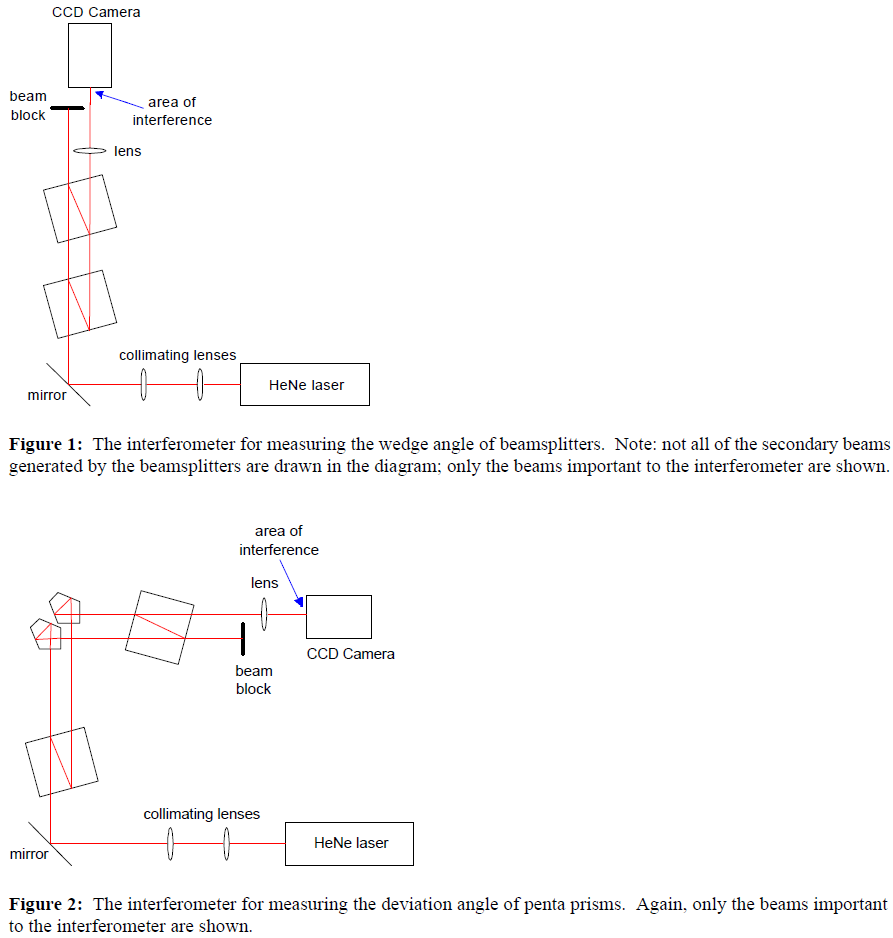
We began by telescoping the beam of a helium neon laser to approximately 1.3 cm in diameter and then insured that the collimation was such that its divergence over one meter was negligible. We then placed one of the beamsplitters into the beam path at an angle to the path, which split off a secondary beam traveling parallel to the first and about 2 cm apart. Then we placed a second beamsplitter farther down the beam path at the same angle, splitting the beam in two again, but this secondary beam overlaps and interferes with the secondary beam from the first beamsplitter, as shown below in Figure 1. The interfering beams were then focused down to fit onto the chip of a CCD camera.
Using LabVIEW™ with IMAQ Vision, we saved bitmap images of the interference pattern, of both of the two interfering beams, and of the background light. At this point, we took three sets of pictures to make sure that the numbers we got were reasonable and to find the standard deviation in the measurement. Then we changed the angle of the second beamsplitter very slightly to image a different part of the interference pattern. We imaged three angles at this position and then slid the second beamsplitter (without significantly changing its angle with respect to the beam) so that the beams were passing through different places on the second beamsplitter’s face. Then we took three sets of pictures for each of three angles at this position and then again at a third position for each beamsplitter.
After saving these files, we use a computer program combining LabVIEW™ and MATLAB® to fit the interference pattern to a two-dimensional cosine function, using a least-squares fitting routine. The angle between the beams is then simply:
The theta in Eq. 1 is the angle due to the combined wedges of the two beamsplitters. In order to determine the wedge angle on each beamsplitter, we flipped the second beamsplitter over to reverse the direction of its wedge and repeated the process. By comparing the theta calculated for each of the three different positions, we could get an idea of whether the measured wedge angle was due to faults in parallelism or in flatness
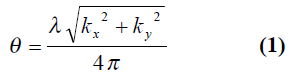
We adapted this method slightly to measure the deviation angles on the penta prisms. In this setup, a penta prism was placed in each of the two beams exiting the first beamsplitter. Then the second beamsplitter was used to recombine and interfere the beams leaving the penta prisms. This setup is shown below in Figure 2.
We again took bitmap images of the interference pattern, of each of the interfering beams, and of the background light using LabVIEW™. We also placed one of the penta prisms on a piezoelectric mount so that we could sweep through a wide vertical angle and take several data points. Then we used a least-squares fitting program to find the minimum, which corresponds to the theta in Eq. 1—a combination of the wedge angles on the beamsplitters and the relative deviation angle between the two penta prisms.
Conclusions
So far, we have measured angles as small as 1 microradian on the beamsplitters with the uncertainty on the same order. According to our data, all six of the beamsplitters are well under our specified limit of 25 microradians. The calculated wedge angles range from 1 to 6 microradians, with an uncertainty of about 1 to 2 microradians. An uncertainty of the same order seems to arise from faults in the surface flatness of the beamsplitters. We have tested one pair of penta prisms, and their relative deviation angle was measured to be 1 microradian, again with uncertainty of 1 to 2 microradians. However, there also seems to be an offset from the mathematical model for the penta prism data. This problem actually casts some doubt on the reliability of our beamsplitter measurements. This discrepancy could be explained by adding a factor for laser beam curvature into our model. If the CCD camera has a nonlinear response, this could also contribute to the error. I am currently researching these possibilities.