C. Porter Bassett and Dr. C. Greg Jensen, Mechanical Engineering
For my project I developed two tools to aid in manufacturing research that is currently being conducted in the Mechanical Engineering Department. This research is about milling, a type of manufacturing where metal is machined bye a spinning cutting tool, very similar to a drill bit, that cuts away the metal. This process generates a lot of heat and causes the cutting tool to heat up. When it heats up, it also expands and changes shape. The change in size of the cutting tool effects how much metal it removes. In precision work, this change in shape can be enough to cause parts to not be within tolerances. Research here is being conducted to quantify how much the cutting tool grows. When it is known how the cutting tool will expand, it can be accounted for beforehand, and it will be possible to machine with greater accuracy.
The first tool that I created is a CAD (computer aided design) model of a cutting tool to be used for FEA (finite element analysis). Finite element analysis approximates the properties of complex shapes by modeling them as a mesh of simple shapes connected together. FEA is used to generate approximate properties such as stress, strain, temperature, or displacement when the conditions acting on the part are known. We plan on using FEA techniques to approximate the shape that the cutting tool should be when the temperatures along the length of the tool are known.
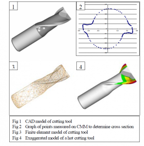
In order for FEA techniques to give useful results, the model has to be accurate. The majority of the work done on this project was to make an accurate CAD model of the very complex geometry of the cutting tool. An image of the model can be seen in figure one. I used the Mechanical Engineering metrology lab to do the measurements in order to create the model. Many measurements were made with manual instruments such as rulers, calipers, and micrometers. However, many measurements required more sophisticated tools.
Much of the measurement was done with a coordinate measuring machine, or CMM. A CMM has probe with a ruby tip that can move in all three directions. The probe is brought down until it touches the part. The probe senses contact, and it records the position of the probe at that point. The position of the probe represents one point on the surface of the part. 3-D data about the surface of the part is measured and recorded. The CMM was used to measure the complex cross section of the tool. Along one cross section, 74 points were taken to measure half of the cross section. Figure two is a graph of the points measured of the cross section. The flat planes on the end of the end mill were also defined using the CMM. Three points were taken on each plane, and the planes were then mathematically defined.
Once all of the measurements were taken, they were used to create a CAD model. ProEngineer is the CAD package that I used to create this model. Once this model was created, it could then be meshed to form a finite element model. This model is pictured in figure three. Analysis using this finite element model is beyond the scope of this project.
The CAD model of the cutting tool was also developed to be used as a visualization tool to depict the thermal growth of the cutting tool. In the research being done, growth after cutting is determined by measuring the diameter of the cutter every tenth of an inch along the tool. I 12 -0.5 -0.4 -0.3 -0.2 -0.1 0 0.1 0.2 0.3 0.4 0.5 -0.6 -0.4 -0.2 0 0.2 0.4 0.6 1 3 4 2 Fig 1 CAD model of cutting tool Fig 2 Graph of points measured on CMM to determine cross section Fig 3 Finite element model of cutting tool Fig 4 Exaggerated model of a hot cutting tool developed my model so that the diameter along each section of the tool could be independently determined. This allows me to change the dimensions of the model to match the actual dimensions of the part after it has grown. I have also changed the model so that as it changes from the original cold dimensions, it changes color. This makes it easier to visually determine how much the cutting tool has grown. Figure four shows a picture of the model representing a hot end mill. In this figure, the growth of the end mill has been exaggerated to show visually how the cutting tool has grown.
Both the finite element model and the visualization tool are useful tools that will be used in the thermal growth research during this next year. In addition, I had the opportunity to learn many useful skills in order to be able to complete this project.

