Derek Wright and Dr. Robert Todd, Mechanical Engineering
Centrifugal force clutches are used around the globe in devices from washing machines to garden tillers. Considering methods of reducing the cost of such clutches, the Utah Center of Excellence for Compliant Mechanism Research developed a fully compliant version, known as the Floating- Opposing Arm Centrifugal Force (FOA) Clutch. Unfortunately, the thickness required for the FOA clutch to perform competitively with comparable clutches makes manufacturing solid FOA clutches slow and costly. To overcome this difficulty, the clutch may be produced as stackable thin layers that sum to the desired performance characteristics. A testing apparatus is required to quantify the performance of the resulting multiple-layer FOA (MFOA) clutch.
Several constraints were considered in the design of the testing apparatus, including: sensing torque, load application, bearing selection and alignment, sensing rotational velocity, process control, and extended cycle cooling. The most influential constraint, however, was the limited availability of a torque source with an adequate rotational velocity (rpm). Since the specific objective of the apparatus is to record the maximum amount of torque transmitted by the clutch at its operating rpm, it is essential to address these factors. Extended cycle and vibration minimizing criteria favored the selection of an electric motor. Several motors were found to be capable of providing the required 6000 rpm or the 50 in-lbs, but not both. Initially, attaching a flywheel to a lower torque motor that met the rpm requirement was considered; this method would use the flywheel inertia to transmit a large amount of torque at the instant that the clutch brake was applied. For the available motor, the flywheel became too large so this idea was abandoned. An adequate solution was found in a 3-hp motor that could produce a projected 140 in-lbs at 1500 rpm. The 6000 rpm requirement was met by using a 4:1 gear ratio, leaving 35 inlbs of torque at 6000 rpm.
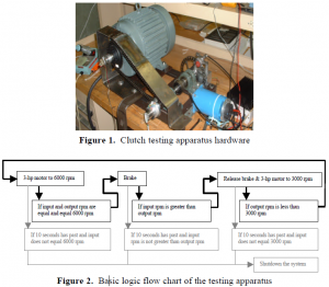
Although there was a commercial solution to the torque source problem, other design difficulties found commercial solutions too expensive or inadequate for this application. As a result, new instrumentation was developed and available resources were modified to the meet the project’s needs. For example, the torque transducer was fabricated because the available alternatives required substantial interfacing and did not provide ample data resolution. Additionally, induced air-cooling of the main bearings allowed their use despite their insufficient rpm rating. The completed hardware is shown in Figure 1.
With the basic hardware in place, the project focus shifted to process control. A programmable microcontroller system was chosen and set to manage the 3-hp motor and a brake actuation motor based on feedback from tachometers on the 3-hp motor and output shaft. The basic test cycle consisted of increasing the rpm through clutch engagement, reaching a maximum rpm, applying a brake, releasing the brake, and decreasing the rpm through clutch disengagement. Process and safety checks were implemented (Figure 2).
The climax of the project was the actual capturing of data. The data consisted of the tachometer and torque transducer voltages with respect to time. The voltages were directed to a laptop computer via a data acquisition card and recorded at 200 Hz with LabVIEW software. Several design flaws were noted. Applying the brake causes the 3-hp motor rpm to dip slightly; therefore, a larger motor may produce more accurate results. Significant signal noise necessitated the implementation of low pass filters on all input streams. Ultimately, however, the testing apparatus effectively cycled and recorded data from an MFOA clutch.

