Jason M. Wiersdorf, Robert Robins, Spencer P. Magleby, Larry L. Howell, and Robert H. Todd
INTRODUCTION
The complex system of bones, muscles, ligaments and tendons in the human ankle allow it to withstand high compression impacts, to move in multiple degrees of freedom, and to transfer energy from the leg to the foot while walking or running.
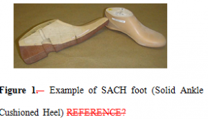
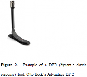
The human ankle is a complex system of bones, ligaments and tendons actuated by muscles enabling it to withstand high compression forces, move in multiple degrees of freedom, transferand transfer energy in walking and running. The prosthetics industry in order to provide a few of these liberties to those who do not have a biologic ankle has produced many foot/ankle systems that provide increased mobility and comfort. The SACH foot, solid ankle cushioned heel, Figure 1Figure 1, is an early prosthetic design, and still one of the most popular due to good performance at a lower price. The foot consists of a stiff core surrounded by a softer foam coating. More recent prosthetic designs include dynamic elastic response or DER feet. DER prosthetics store energy in the form of a deformed leaf spring during the midstance phase and release that energy through plantarflexion during the propulsive phase (Figure 2Figure 2) [11]. Many models have a foam heel to dissipate energy at the contact phase.
Simultaneous to prosthetic advances is advances in compliant mechanism research. Compliant mechanisms use the compliant (bending) properties of a material to transfer motion or energy. Primary advantages of compliant mechanisms are their low cost to manufacture and assemble, and their minimal maintenance requirements.
Compliant mechanisms offer potential advantages in some applications including cost reduction and improved performance. Cost reduction generally comes from a part-count reduction, assembly time reduction, and simplified manufacturing processes. The improved performance is realized through increased precision and reliability, and reduced wear, weight, and maintenance.
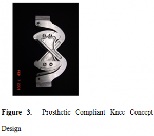
The umbrella of compliant mechanism application continues to broaden from living hinges on shampoo caps to orthoplanar (reference paper) springs in continuous variable clutches. This paper explores the application of compliant mechanisms in prosthetic devices. Guérinot, A., laid groundwork for the research with his design solutions for high compression compliant mechanisms HCCM [1]. In a case study, Guérinot designed a prosthetic knee as a test platform for his HCCM designs (Figure 3Figure 3). Guérinot’s design solutions include inversion and isolation which will be discussed later in this paper.
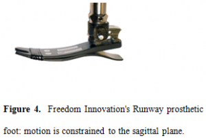
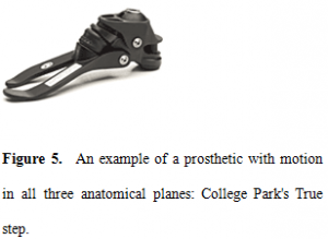
The simplest model for the ankle joint, after which many prosthetics are modeled, is a simple hinge representing one degree of freedom in the sagittal plane – allowing only plantarflexion and dorsiflexion (see Figure 4Figure 4). More complex models allow motion in all three anatomical planes, such as the College Park Trustep (Figure 5Figure 5). These designs are often made possible through new materials such as carbon fiber.
The goal of the compliant prosthetic ankle is to provide motion in all three anatomical plains and to accomplish this by using compliant mechanism joints. Compliant mechanism joints typically have fewer parts than traditional pin joints and subsequently have a lower cost to manufacture and assemble, and require lower maintenance.
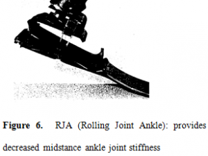
Advances in biomechanics allow for mechanical designers to create devices that more closely model the human ankle. Research in kinematics of the ankle allow for designs based on typical joint rotations and joint moments. It has been suggested that designing prosthetic ankles that more closely mimic the kinematics of the human ankle may reduce trauma on related joints such as the knee as well as the prosthetic/stump interface area [8](FIND other REFERENCEs). An example of a design that mimics the biological ankle is the rolling-joint ankle, RJA, designed by M. R. Pitkin [9]. Pitkin recognized that current prosthetic feet/ankles are not satisfying the important aspect of moment resistance to dorsiflexion in biological gait. In normal walking or running, movement in the sagittal plane includes a period of low joint resistance followed by a period of high joint resistance or deceleration [13]. The RJA joint was designed to mimic the biologic ankle by providing decreased midstance ankle joint stiffness and as a result reducing negative reactions on the knee joint.
The objective of the preliminary research described in this paper is to explore the potential of using compliant mechanism systems to design prosthetic ankles based on human kinematics and to provide direction for pursuing the design of such systems. In particular, this paper will outline a kinematic model which is the foundation of current compliant prosthetic ankle designs and introduce MERA, Modular Experimental Research Ankle, which has been designed to allow examination of the motion and moments of multiple compliant joints within a prosthetic ankle.
ANKLE BIOMECHANICS
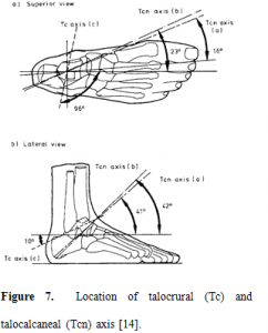
Since the “design of a prosthetic foot, ankle and shank should reproduce a gait pattern as normal as possible…,” while simultaneously lending itself to compliant mechanism use, a two rotational axis model, proposed by Dul and Johnson, is used [4, 5, 6]. The model is based on the center of rotation of the talocrural (tibiotalar) and the talocalcaneal (subtalar) joints (Figure 7Figure 7). The orientation of the two axes alloworientation of the two axes allows the foot to pronate and supinate (combination of movement in all three anatomical planes). This model was chosen because of its simplicity in that tri-planar motion is gained with only two axis of rotation. Of course, this model only applies to normal gait, and therefore all designs and prototypes presented in this paper are modeled for walking.
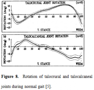
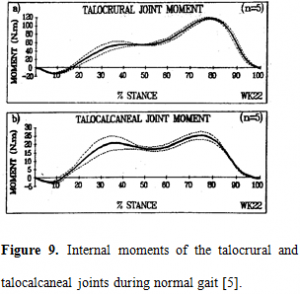
Scott and Winter [5] found the rotation and moment about the tibiotalar and subtalar joints using the same two axis single degree of freedom joint model. Results are shown in Figure 8Figure 8 and Figure 9Figure 9. Their joint rotation and moment results are the basis for the compliant modular fittings in MERA discussed below.
MERA: DESIGN AND BENEFITS
The two rotational axis model and the experimental results were used to design modular fittings in a modular experimental prosthetic ankle (MERA).
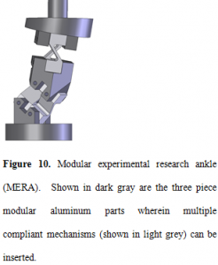
Developing a compliant prosthetic ankle joint naturally lends itself to a modular setup wherein a variety of compliant mechanisms can used; to this end a modular experimental ankle (MERA) was developed as shown in Figure 10 interface enabling easy assembly and testing of different compliant ankle joints.
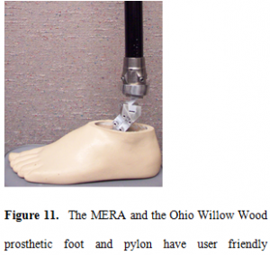
As shown in Figure 10Figure 10, the MERA is a three piece aluminum module that is mountable with the Ohio Willow Wood prosthetic foot and pylon (which uses standard prosthetic mounts). The lower and upper units are rigidly connected to the foot and pylon respectively, and the addition of a third piece permits a multi-axial model wherein compliant mechanisms can readily be positioned with set screws. The MERA design benefits are two-fold: it follows the two-axis kinematic model of the human ankle while simultaneously lending itself to different compliant joints. The MERA methodology provides the ability to turn an idea into something tangible that can then be subject to testing and evaluation.
The MERA is designed to enable the testing of different compliant joints subject to the following performance specifications: (1) compliant joint must be compact and fit inside the MERA mounts [3-reference to mount dimensions], (2) must allow for approximately 10 degrees pronation, 10 degrees supination for the talocrural joint and 5 degrees pronation 10 degrees supination for the talocalcaneal joint (Figure 8Figure 8) (3) must withstand moments of 120 Nm in pronation and 20 Nm supination for the talocrural joint, and 25 Nm in pronation and 5 Nm supination for the talocalcaneal joint (Figure 9Figure 9).
In order to fulfill the said performance specifications the following compliant joints have been considered. These joints currently fit inside the MERA mounts and allow motion observation. Improvements to fulfill design requirements 2 and 3 will be discussed.
The MERA design integrates rigid members with swappable compliant pieces in order to provide for quick prototyping and testing. This modular interface allows for simplified part designs which lend themselves to easy machining.
FUTURE USE OF MERA
The modular experimental research ankle has been designed for the primary purpose of studying motion. A model that can provide the desired motion can then be adapted and enhacedenhanced. In order to create an accurate model three key areas will be considered: 1) enhance stiffness, 2) limit motion, and 3) enhance compressive capabilities.
[Discuss in general how we are currently looking at motion and why and then introduce the sections you speak next (enhanced stiffness, limit motion…)]
Enhance stiffness
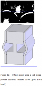
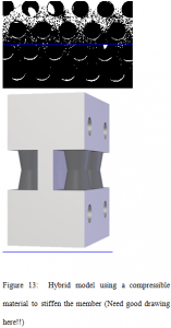
One of the key areas of concern with the current prototypes is the lack of stiffness provided by the compliant member. Despite the fact that the prototyped members are made from polypropylene, even a metal prototype will not provide the degree of stiffness that a prosthetic ankle requires. For this reason the MERA will be used as a test bed for developing stiffer concepts. Among the possibilities of increasing the stiffness of the compliant members are the following: 1) thicken the compliant member, 2) add additional compliant members, and 3) add a stiffening mechanism independent of the compliant member. Examples of Tthe third option allows for a hybrid type design where the compliant members’ stiffness is enhance by the stiffness of a different mechanism that is added in series as isare shown in Figure 12Figure 12 and Figure 13Figure 13. [Last sentence a little “wordy”, consider revising.].
The design concepts shown in Figure 12Figure 12 and Figure 13Figure 13 in Figure 14 is a design concept that not only enhances stiffness but has ve the added benefit of an adjustability factor within the second member. Having the second adjustable member would allow the user to adjust the compliant ankle to meet their personal preference. The Compliant member in Figure 14 is supplemented with an adjustable CAM mechanism that can be move so as to “stiffen” the compliant member. [probably need a picture to illustrate CAM idea – difficult to see idea with figure 14]
Limit Motion
Though unintuitive, pProsthetic ankle joints are not only very stiff butand they only provide a very limited range of motion which . [is attributed to This is probably due to strict ISO testing standards.] Though stiffness and limiting motion can readily be coupled in many designs, they may also be considered independent of each other. Therefore, in order to limit the range of motion, the MERA will also be used to test concepts that can provide a restricted range of motion independent of stiffness.
Enhance compressive capabilities
The MERA is a research tool, not a prosthetic; nevertheless, it must be able In order for the MERA [It should be clear in your sections that MERA is not a prosthetic, but a research tool. No one will ever wear MERA, but may wear a design that comes from MERA] to support the weight of the human body the compliant members must be able to endure high compressive forces. Conventional compliant members are inherently prone to buckling under high compressive loading, therefore the MERA will consider two principles used in the design of compliant members in order to handle higher compressive forces; these principles are (1) isolation and (2) inversion.
Isolation [Do we have any ideas on how we might use isolation with MERA, rather than just explaining what isolation is? – maybe explain how figure 15 relates to the ankle]
The isolation principle essentially makes use of rigid body members in order to ‘isolate’ the compliant member from buckling while still taking full advantage of the compliant members ability to store energy and provide for motion constraints. A schematic of the isolation principle is shown in Figure 14Figure 14 with the red arrows representing the direction of loading. There is a whole class of compliant mechanism that makes use of the isolation principle and the MERA will serve as the testing grounds for these concepts.
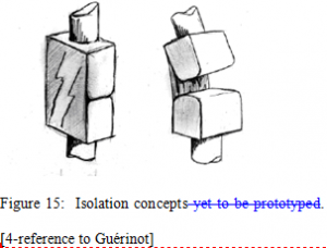
A specific examples of the isolation principle are is shown in Figure 15Figure 15. This concept will be prototyped and tested in the MERA in order to compare its performance against other compliant concepts. Along with isolation other supporting elements can be used to increase compressive capabilities in a compliant ankle joint in order to endure extremely high moments on the multi-axes model. [What do you mean by “other supporting elements”? What are they?]
A specific examples of the isolation principle are is shown in Figure 15Figure 15. This concept will be prototyped and tested in the MERA in order to compare its performance against other compliant concepts. Along with isolation other supporting elements can be used to increase compressive capabilities in a compliant ankle joint in order to endure extremely high moments on the multi-axes model. [What do you mean by “other supporting elements”? What are they?]
Figure 15: Isolation concepts yet to be prototyped. [4-reference to Guérinot]
Inversion
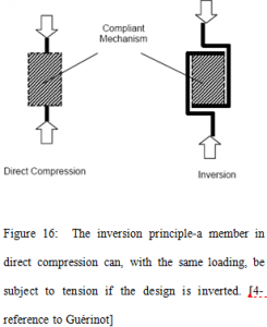
Inverted compliant members are yet another category of future prospects for the MERA. The inversion principle, like isolation, is an additional method of evading buckling prone compliant member designs. As shown schematically in
Figure 16
Figure 16, the basic idea behind inversion is to “invert” a compliant member in order to transform a compressive load into a tensile load. This is done in light of the fact that the maximum tensile force a member can tolerate is greater than the critical buckling force; therefore, when inverted, the members’ performance is enhanced considerably.
Figure 16: The inversion principle-a member in direct compression can, with the same loading, be subject to tension if the design is inverted. [4-reference to Guérinot]
Figure 17: Prototyped Compliant joint based on the inversion principle.
The first concept prototyped for inversion is shown in Figure 17. This is only one of many inversion concepts to be tested on the MERA. In the end [End of what?]. T testing with the MERA could also lend s itself to a hybrid of compliant members and traditional joints.
REFERENCES
- Guérinot, A. E., 2003, “Compliant Mechanisms Subjected to Compressive Loads,” M.S. Thesis, Brigham Young University, Provo, Utah.
- Guérinot, A. E., Magleby, S. P., Howell, L. L., and Todd, R, H, 2004, “Compliant Joint Design Principles for High Compressive Load Situations,” Journal of Mechanical Design, in press.
- Guérinot, A. E., Magleby, S. P., Howell, L. L., and Todd, R, H, 2004, “Preliminary Design Concepts for Compliant Mechanism Prosthetic Knee Joints” Proceedings of DET-143C’04
- Dul, J., Johnson, G.E., “A Kinematic Model of the Human Ankle,” Journal of Biomedical Engineering 7, 137
- Scott, S. H., Winter, D. A., 1991, “Talocrural and Talocalcaneal Joint Kinematics and Kinetics During the Stance Phase of Walking,” Journal of Biomechanics Vol. 24, No. 8, 743-752
- Czerniecki, J. M., 1988, “Foot and Ankle Biomechanics in Walking and Running,” American journal of physical medicine & rehabilitation Dec; 67 (6):246-52
- Di Gregorio, R., Parenti-Castelli, V., O’Connor, J.J., Leardini, A., 2004, “Equivalent Spatial Parallel Mechanisms for the Modeling of the Ankle Passive Motion,” Proceeding of DETC’04
- Quesad, P. M., Pikin, M., Colvin, J., 2000, “Biomechanical Evaluation of a Prototype Foot/Ankle prosthesis,” IEEE Transactions on Rehabilitation Engineering, Vol. 8, No. 1, 156-159
- Pitkin, M. R., 1996 “Synthesis of a Cycloidal Mechanism of the Prosthetic Ankle”, Prosthetics and Orthotics International, 20, 159-171
- Cannan, J. R., 2004, “In-Plane Compliant Mechanisms to Replace Bearings and Springs in High Precision Applications” M.S. Thesis, Brigham Young University, Provo, Utah
- Geil, Mark D, PhD, 2001, “Energy Loss and Stiffness Properties of Dynamic Elastic Response Prosthetic Feet” Journal of Prosthetics and Orthotics, Vol. 13, Num. 3, 70-73
- Apkarian, J., Naumann, S., Cairns, B., 1989, “A Three-Dimensional Kinematic and Dynamic Model of the Lower Limb” Journal of Biomechanics, Vol. 22, No. 2, 143-155
- Winder, DA, 1979, Biomechanics of Human Movement – New York: J Wiley
- Procter, P., Paul, J. P., 1982, ”Ankle Joint Biomechanic” Journal of Biomechanics, Vol. 15. No 9, 627-634

