Gregory J. Larson
The IsoTruss Panel is a three dimensional composite grid structure, evolving from the IsoTruss®. The IsoTruss® implements a revolutionary idea of utilizing the very strong unidirectional characteristics in composite materials in a three dimensional manner. The IsoTruss® is utilized in pole-type applications. The IsoTruss Panel is based on similar principles but is designed for use in plate and wall type structures as well as curved applications.
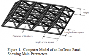
The basic geometry of the IsoTruss® Panel are repeating four sided pyramids with a top and bottom grid, shown in Figure 1. It is composed of two main types of members: Longitudinals and Helicals. The longitudinal members are the straight sections which lie in either the top or bottom grid created by the Panel. The helical members are the members which create the pyramid shape and bridge the gap between two grids of longitudinal members. Joints are the points of intersection where longitudinal and helical members come together. The bay length is the length of the base of one pyramid in each direction, and the number of bays refers to the number of pyramids in each direction (i.e. Figure 1 shows an IsoTruss® Panel with four bays in each direction).
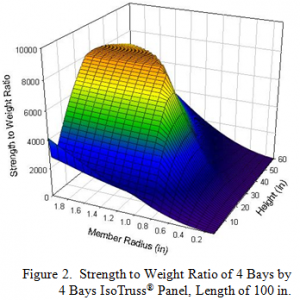
A parametric study was conducted on the IsoTruss® Panel looking at the strength for various configurations. In this study the overall length of the structure was maintained at 100 in (254 cm) while the length of one side of the square, height and member diameters were varied in the IsoTruss® Panel. It was then loading perpendicular to the grid planes using an equal point load at each joint on the top grid. The failure load was the sum of the point loads required to cause failure. This method was done to discover trends in the structure to determine the potential of the structure.

While the height and diameter of members is an obvious change, the method used to change the length of one side of the square while maintaining the overall height was to change the number of bays in each direction. To truly optimize the IsoTruss® Panel one would need to also independently change the diameter of the members of the longitudinals in each direction as well as the helicals, vary the bay length in each direction, not necessarily maintaining a square, as well as a variable height throughout the structure. However, the variables chosen were varied to discover general trends of the structure.
Originally the finite elemental analysis was to be performed on Catia V5, however, afterwards it was discovered Catia cannot perform a buckling analysis—a critical aspect of any grid structure. As an alternative, Abaqus was chosen as the finite element analysis package.

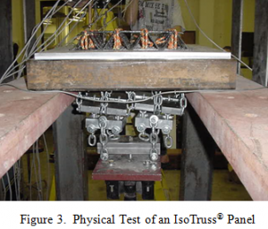
The main set of analyses were performed using an overall length of 100 in (254 cm), as previously stated. Additional analysis was performed for an overall length of 16 in (40.6 cm), height of 2.375 in (6.03 cm), and a bay length in each direction of 4 in (10.2 cm), where only the radius was varied, due to an existing mandrel built for this size IsoTruss® Panel. From these analyses the size of IsoTruss Panel to be built was decided to have a member radius of 0.1 in (0.254 cm). The test set-up for this structure is shown in Figure 3.

The theoretical failure load was determined to be 16,700 lb. The actual failure load was 5,250 lb. It is typical for any of the IsoTruss® physical tests to not be as strong as the theoretical strength. However, they are not typically this low. A large reason the physical test case did not hold as much strength as expected were that the diagonal members of the structure were not very straight due to the manufacturing process and mandrel.
More Optimization could be performed on the IsoTruss® Panel, including, varying the member radius of the horizontal and diagonal members independently, varying the height throughout the structure, and analyzing different configurations of the IsoTruss® Panel. Comparisons with currently used structures should be conducted to determine its possibility in replacing current designs.
