Donald B. Conkey and Dr. Aaron R. Hawkins, Electrical and Computer Engineering
Electroosmotic pumps have been fabricated and tested made with a thin-film deposition process compatible with standard silicon processing. This methodology relies upon chemical vapor deposition and chemical sacrificial etching to form long hollow fluid channels. Fabricating pumps in this way is attractive because they can be made on a variety of substrates with high-scale integration and can conveniently be combined with other planar thin-film components. These pumps have significantly smaller core diameters and separation between micropump channels than pumps made with alternative fabrication techniques. Flow rates were measured on these devices for different applied voltages.
The process for creating electroosmotic pumps is fairly straight forward. Glass wafers are used. First, these wafers are cleaned and a thin layer of Silicon dioxide (100 nm) is grown using plasma enhanced chemical vapor deposition. Originally silicon wafers were used, but these were replaced with the glass wafers as problems with current jumping through the insulating oxide layer and going through the silicon arose. This bypassed the buffer in the electroosmotic pump completely and caused no pumping.
Following this a 200 nm layer of aluminum is evaporated onto the wafer using thermal evaporation. A layer of AZ3330, a photoresistive substance, is then applied. Some areas of the wafer are then exposed to UV light which causes the photoresist to go through some wavelength specific radiation-sensitive chemical reactions. The areas of photoresist that were exposed to light turn more acidic. The wafer is then dipped in an alkaline developer which removes the more acidic exposed portions of AZ3330. The wafer is than placed on a hotplate to bake and solidify the remaining AZ3330. This leaves the aluminum exposed with some areas having AZ3330 remaining.
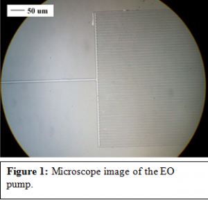
The wafer is then dipped in and soaked in an acidic solution. Those areas of aluminum which were not covered by the AZ3330 are etched away. This leaves areas of aluminum shaped exactly like the exposed AZ3330 on the wafer. These aluminum areas and AZ3330 photoresist become the cores of the electroosmotic pumps (Al/PR core). The shapes look like microscopic forks. With the stem being either 10 um wide and 12 mm long and the tines being 4 um wide and 5 mm long. Each microscopic fork has 50 tines. Figure 1 shows a microscope image of the electroosmotic pump. These specifications came from testing many different shaped EO pumps and determining which worked the best. More oxide is deposited onto the wafer to cover the Al/PR cores. The Al/PR cores are then completely surrounded by oxide 3 – 4 ums thick. The thicker this layer is the stronger the pump can be.

The Al/PR cores that have been covered with oxide need to be exposed to allow for the cores to be removed. To do this AZ3330 is placed on the wafer again, over the main body of the pumps, but not covering the extreme edges. The wafer is baked to solidify the photoresist and the wafer is then dipped in HF, which etches the oxide layer until the ends of the Al/PR cores are exposed.
After this the wafer is taken and put into another acidic solution called Aqua Regia(HCl/HNO3) which etches the aluminum out of the cores. This can take several days to accomplish. After the aluminum is etched the wafer is placed in Nanostrip(H2SO4/H202), which etches out the remaining photoresist core. At this point the channels are hollow. All that remains are reservoirs for the liquid solutions. These are placed over each end of the pump. The reservoirs are made from glass beads which are stuck on using a combination of silicone and epoxy.
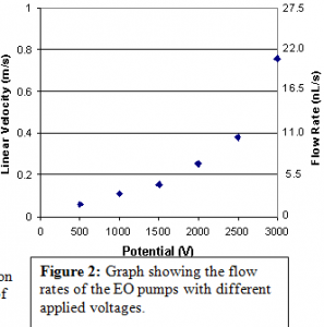
After this process the electroosmotic pumps can be tested. This is done by filling the reservoirs with an ionized buffer solution and placing a voltage differential at the opposite ends of the pump, in the reservoirs. The oxide surrounding the channels is negatively charged and attracts the positive ions. The applied voltage differential creates an electric field which causes the positive ions to flow towards the more negative potential. This movement pulls the bulk of the fluid with it, causing pumping. This was tested with various voltages and flow rates were calculated for each as can be seen in figure 2.

These results were presented on a poster at the 28th International Symposium on Capillary Chromatography and Electrophoresis in Las Vegas in May. They were also published in the journal, Lab on a Chip. I also gave a presentation to a group of student researchers on this research in May.
