Kasey Greenland and Dr. Mark Colton, Mechanical Engineering
Many upper-limb amputees are fitted with body-powered prostheses. These are typically operated by the user wearing a harness and making a certain body movement. That movement pulls a cable which then moves the terminal device, which may be an artificial hand or a hook, to perform desired functions. With such prostheses the user is typically limited in their use of the individual fingers and many opt for a hook. Some have voluntary-closing terminal devices, meaning that the hand is in an open position when no force is applied . Though these devices are useful, they often do not provide the grasping capability that is desired due to friction losses in the mechanism and in the rubberized hand. Also, the user must continue to apply a force to hold an object. If an object is held for an extended period of time, it causes fatigue in the user. As a result, body-powered prostheses limit the ability of the user to perform desired actions.
There are also voluntary-opening devices, where the hand is closed when no body-powered force is applied1. This resolves the problem of fatigue when holding an object, but poses another problem of generating enough force to open the hand to the desired position. It also makes it difficult for the user to vary the force with which the hand grips an object. My proposal was to create system where the user’s body power is supplemented by another power source in order to create the desired force and minimize fatigue. This can result in greater comfort for the user and a greater ability to perform desired tasks.
The process of designing this system began with considering ways to amplify force. Various ways of amplifying force were examined including using fluid, pulleys, and gears. In each of these cases the force could be increased, but the user would be required to make a greater movement to do so. Since the user is limited in the amount of distance they can pull the cable, these options were not practical.
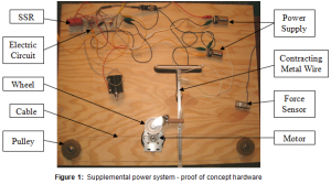
It was determined that either an electric motor or a linear actuator would be a good means of applying an amplification force. Also, there would need to be a sensor to determine either the force or displacement that was input from the user. It was found that a force sensor (Fig. 1) would be better because it would allow the assistive device to give an output force proportional to the input force from the user.
Once the sensor had been determined it was necessary to generate concepts for applying the amplification source to the cable. As the concepts were generated additional design specifications were discovered. It was noticed that if the motor or actuator were always connected to the cable it would provide a resistance force to the user until it was given power. This posed a problem because it was desired that the motor or actuator wouldn’t provide assistance until the force exceeded a certain threshold. It was realized that if any mechanical system were used to engage the motor or actuator it wouldn’t be able to disengage when the input force dropped below the desired threshold until it reached the point of engagement. It became clear that there needed to be an additional actuation device to engage or disengage the motor or actuator. This was accomplished using a special metal wire that contracts when heated. This was used to pinch the cable between the motor and a wheel resulting in the cable moving.
In addition to the mechanics of the system an electrical circuit (Fig. 1) was designed and created so that the motor (Fig. 1) would turn only when the desired input force was exceeded. This was accomplished by taking the force sensor input and amplifying the electric signal. That signal was given to a solid state relay (SSR) which only gives an output when the input exceeds a certain voltage. The output voltage from the SSR (Fig. 1) was directed two ways. First, it went to a component which allows for a variable output based on a variable input. This was connected to the motor and allows the motor to turn at a rate proportional to the user input force. Second, the SSR output was put across the contracting metal wire (Fig. 1), causing the motor and wheel (Fig. 1) to engage with the cable.
Basic proof of concept hardware was designed and built showing that the concept is valid. The parts used for the proof of concept system are larger and heavier than would be allowable in a prosthetic device, but there are some definite areas where both the size and weight could be drastically improved. These areas could use more development, but the hardware shows that the system itself would work. It would be great if this system could be manufactured to fit current body-powered prostheses and implemented for a low cost. An advantage of this system is that it would allow the user to have additional force if desired and they could also use the prosthetic device even if the battery died. Current electric prostheses are quite capable, but are heavier than body-powered prostheses and don’t work without electric power. This system would incorporate the best of both designs to give the user the capability and comfort while keeping costs low.

References
Wilson, A. Bennett, Jr. A Primer on Limb Prosthetics. Illinois: Charles C. Thomas Publisher Ltd, 1998.
