Ryan B. George and Dr. Scott L. Thomson, Mechanical Engineering
Ladybug wing and body kinematics during takeoff is explored using high-speed stereoscopic imaging. Recordings of the specimens during flight are acquired at a rate of 3000 frames per second. A direct linear transformation algorithm is performed using custom implementation in Matlab to quantify positions of selected locations on the body, forewings (elytra), and hindwings. Design and setup of instrumentation and analysis procedures are explained. Flapping frequency is reported. Significant motion of the elytra and other findings are presented and their applications are discussed.
Nomenclature
[x y z] = coordinates in Cartesian space (cm)
uL, vL = x, y position of object in left view frame (pixels)
uR, vR = x, y position of object in right view frame (pixels)
L = Left image calibration vector
R = Right image calibration vector
I. Introduction
The use of flapping flight is ubiquitous among the animal and insect kingdom1. Flapping flight, which features an aerodynamic flight regime characterized by a relatively low Reynolds number, yields lift-generating mechanisms. It introduces several advantages such as increased agility and the increased ability to navigate in confined spaces (such as indoors). It also brings decreased detectability in the application of micro air vehicles (MAVs) due to reduced size and possible reduced noise and the ability to hover and/or perch-and-stare.
Many aspects of flapping flight kinematics, both in natural and man-made systems, however, are yet to be fully understood. Such aspects include deformable and/or adjustable wings and wing kinematics, the wide variability in wing size, wing shape, and wing and body kinematics. One particular aspect of interest is the influence of the forewings found in beetles (Coleoptera). Flying beetles such as ladybugs (Hippodamia convergens) have two stiff, protective forewings and two flapping hindwings. The forewings, known as elytra (or elytron, singular), cover the hindwings when not in flight, but move upward and forward during flight. They also perform other functions such as trapping moisture, protection, etc.2 The role of the elytra during flight, however, has not been rigorously explored; nor have the wing kinematics and aerodynamics of the elytra-hindwing combination.
The goal of the present research is to analyze beetle flapping wing kinematics using ladybugs as subjects. We have analyzed a series of high-speed images of a ladybug during takeoff to quantify the three-dimensional position of two points on the body, one elytron, and one hindwing. Kinematic results and observational findings are presented.
II. Methods
A. Overview
The approach of the present research is to analyze flapping wing kinematics using a stereoscopic method involving a high-speed digital camera. A direct linear transformation (DLT) is applied in order to correlate the twodimensional stereoscopic image coordinates into three-dimensional Cartesian spatial coordinates. The goal is to convert this data into appropriate kinematic representations for use in investigating the role of the forewing in flapping flight and to study deformable wing shape kinematics of ladybugs.
B. Data Acquisition
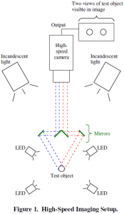
As illustrated in Fig. 1, the experimental setup involves a Photron APX-RS high-speed digital camera, a mirror arrangement for projecting two views of an object onto a single camera image, and a combination of LED and incandescent lighting. The frame rate of the camera is set to 3000 frames per second while the shutter speed is 1/6000th of a second. This higher shutter speed ensures a relatively complete freeze of the wing motion. A Nikon 105mm Nikkor lens is used with an aperture of F11.
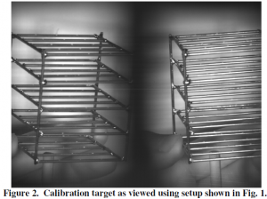
Prior to image acquisition, a calibration target was created using 1/16th inch diameter extruded wire soldered together to form a grid pattern. The target consists of 5 tiers with 25 white dots painted on each tier, providing a total of 125 calibration points. The target was placed in the camera’s field of view, so that two views of the target are visible in the camera image (see Fig. 2).
C. Data Analysis
Matlab is the primary tool used to analyze high-speed images. A Direct Linear Transformation (DLT) implementation, custom coded in Matlab, is used. DLT procedure is briefly described; further details can be found elsewhere3,4.
DLT is a method of determining the three dimensional location of an object (or points on an object) in space using two different views of the object. There are a variety of ways of attaining multiple images; however, the approach used here is one camera and an arrangement of mirrors. This allows for the relative distances between the camera, mirrors, and object to be varied over a sufficiently wide range. This method is also beneficial since it requires only a single camera it requires no synchronization between sets of images.
Calibration is found using 100 visible calibration points on the aforementioned calibration target. Calibration consists of finding vectors L and R using the following series of equations. First,
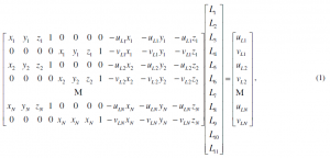
is calculated, where N is the number of calibration points, xi, yi, and zi (i = 1 to N) are the known positions of the calibration points, uLi and vLi are the horizontal and vertical pixel locations, respectively, of the points in the images, and L1 through L11 are the calibration constants. Similarly, R (R1 through R11) is found by replacing vLi, vLi, and L with uRi, vRi, and R. If we denote the first matrix on the left-hand side as FL and the right-hand side matrix as gL, then using the Moore-Penrose pseudo-inverse method:
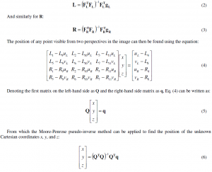
In the present research, the L and R calibration matrices are found using the calibration target. A ladybug is then placed in the field of view and images of the ladybug are acquired during takeoff. The x, y, and z locations of four points on the ladybug are then tracked. The points include a point near the front of the body, a point near the rear of the body, the tip of the left elytron, and the tip of the left hindwing.
III. Results
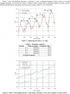
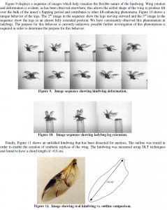
We have had success in the acquisition and analysis of high-speed video of several ladybugs during takeoff. Accomplishments include (i) calibration of L and R vectors using calibration target; (ii) DLT analysis of 180 frames of data (about 0.06 seconds) which include 4 cycles of flapping motion for one ladybug; (iii) flapping frequency analysis; (iv) exploration of vertical displacement of one elytron and one hindwing; (v) analysis of body velocity; (vi) observation of flexible wings and unique ladybug leg motion during flight; and (vii) analysis of wing geometry.
The figures that follow are presented here to demonstrate success in the areas listed above. Figure 3 shows the known positions of the points on the calibration target. Returning the pixel locations of the calibration points into Eq. (6) allows for an estimate of the quality of the calibration data. The comparison between actual and calculated points is adequate.
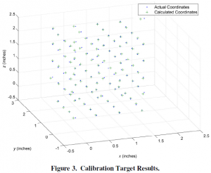
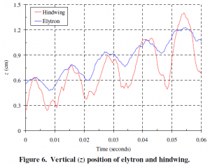
Figure 4 shows two images of the ladybug; one at data analysis initiation, and another at the last frame of data analysis. These images show the coordinate system used. Figure 5 plots a time history of the positions of the four points on the ladybug during takeoff. This demonstrates successful implementation of image analysis of the ladybug specimen. It is interesting to note that the elytron moves in unison with the hindwing with a relatively large amplitude. This may be a passive reflex, although further investigation is required to determine this. Figure 6 shows an exploration of vertical displacement of both elytron and hindwing.
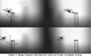
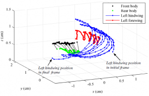
Figure 5. Symbols showing three-dimensional paths of four ladybug anatomical landmarks. The dashed black lines connect the front and rear body points, illustrating the approximate ladybug attitude, at select times.
IV. Conclusion
The work presented represents the results from data acquired from a series of high-speed images of a ladybug during takeoff. These results illustrate the functionality of the DLT implementation and calibration technique, the successful data acquisition of a ladybug in takeoff and free flight, and show a thorough analysis of the data. It is anticipated that this data will be useful in investigating the aerodynamics of insect flight, including the development and analysis of computational and experimental models. Of particular interest will be the aerodynamics interaction of the relatively stiff (but not static) elytra-generated vortices with those generated by the much larger hindwings. The current data measure the three dimensional position of the specimen in free flight and give a brief analysis for four cycles of flapping motion.
Acknowledgements
R. B. G. expresses gratitude for the BYU ORCA award that facilitated this research. The findings reported here have been submitted as a conference paper to the 48th American Institute of Aeronautics and Astronautics (AIAA) Aerospace Sciences Meeting (January 2010).
References
- Shyy, W., Lian, Y., Tang, J., Viieru, D., and Liu, H. Aerodynamics of Low Reynolds Number Flyers, Cambridge University Press, Cambridge, 2008, Chapters 1,4.
- Frantsevich L, Zhendong D, Wang W, and Zhang Y. “Geometry of Elytra Opening and Closing in Some Beetles”, The Journal of Experimental Biology, Vol. 208, 2005, pp. 3145-3158.
- Abdel-Azez, Y. I. and Karara, H. M. “Direct Linear Transformation from Comparator Coordinates into Object Space Coordinates in Close-Range Photgrammetry,” Proceedings of the ASP/UI Symposium on Close-Range Photogrammetry (American Society of Photogrammetry, Falls Church, VA), 1971, pp. 1-18.
- Hartley, Richard. Zisserman, Andrew. Multiple View Geometry in computer vision, Cambridge University Press, Cambridge, 2003.

