Brett T. Walkenhorst and Dr. David V. Arnold, Electrical and Computer Engineering
Scatterometry is a method used today to track and predict global warming, storms, and other important factors in the earth’s climate. NASA currently has a scatterometer in orbit around earth called QuikScat. There are many useful applications of scatterometry, but there are still many environmental factors that interfere with the scatterometer’s data that we don’t completely understand and can’t account for yet. For this reason, NASA is funding a research project called YSCAT, BYU’s own scatterometer. YSCAT will be deployed on a dock off the coast of southern California and will be used to collect data from the ocean waves. This data will help researchers fine tune the data processing to give more accurate results from the scatterometer. The research currently being conducted is to construct a working prototype of this radar.
Although the entire radar system has not been completed, some important developments have been made. This report will focus on the development of the transmitter, a frequency modulated continuous wave chirp generator.
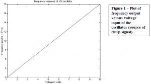
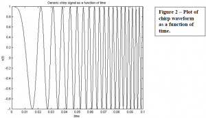
All radars use a “chirp” signal to transmit and receive data. A “chirp” is an electrical signal or electromagnetic wave with a single frequency that increases linearly with time. The focus of this transmitter was to linearize the chirp signal as much as possible in order to eliminate data errors that arise from nonlinearities in the receiver. The frequency response versus voltage is plotted below as well as a time representation of the chirped signal.


The linearization of the chirp signal is based on a feedback loop that counts the frequency and corrects the signal accordingly. The initial idea was to set the voltage level, count the frequency, compare to a desired frequency, and update the voltage. This would be repeated until the desired frequency was achieved and that entire process would be repeated 128 times to give 128 voltage levels. This is called “static” calibration to ensure linearity. It was quickly discovered that a static calibration was good, but it wouldn’t be enough to achieve the accuracy we need, so we began to design a circuit which could be calibrated “dynamically”. This would measure the frequency over a part of the chirp and update the voltage levels as the oscillator was chirping. This would solve the linearity problem, but the design becomes a little more difficult.
Now the period over which we can count is constrained by the time it takes to chirp the range of frequencies or the “chirp rate”. Using a static calibration, we could specify an arbitrary period which meant we needed very few significant bits in the frequency counter. In this routine, the circuit divided the frequency down to a few megahertz before it counted. With the dynamic calibration routine, the period over which we can count is specified and we need to be able to count higher frequencies rather than just dividing the frequencies down. Based on calculations and preexisting conditions, it became necessary to count as high as one gigahertz (almost a thousand times the previous frequency).
The frequency counter being used before was TTL which is very standard digital logic that ranges from zero to five volts. It is impossible to count as high as we need to with TTL logic, so a new family of logic known as the “black magic” of logic had to be used. This logic is called ECL or “emitter coupled logic”. Not much is known of ECL, but because of the faster switching capability of this logic, transmission line theory needs to be used because of the higher frequency capabilities. This became a fairly complicated process to experiment and learn about this logic in order to count the frequency of the oscillator so that it could be updated dynamically. After many hours and lots of debugging, we were able to accurately count the frequency or phase progression and incorporate this new calibration routine. Based on measurements, the chirp is sufficient for accurate measurements and now the receiver needs to be built and the system will be integrated and deployed.
