Ruth Bell and Dr. Doran Wilde, Electrical and Computer Engineering
A number of approaches to constructing high performance recursive digital filters have been attempted. An approach using piplelined multiply-accumulate blocks in which computations are performed most significant digit (msd) first has demonstrated important benefits. A recent computer journal article describes 1 msd first multiply accumulation and presents the basis for a systematic method of deriving VLSI architectures for low latency, pipelined recursive systems.
I have used the theory presented in this journal article as the basis for the design of a pipelined bit parallel second order digital filter circuit. This paper summarizes the results of the design, which was simulated and tested using VHDL, a hardware description language.
The filter performs the multiply-accumulate function M = X # Y + A, where M is the final result, X is the input signal, Y is the multiplier, and A is the addend. In this design, M, X, and Y are represented using 12 bits and are less than 1 in magnitude. The addend A was chosen to be 7 bits. The magnitude and number representations of these signals determines the computational latency of the overall circuit.
The signals are encoded in such a way that accuracy is preserved throughout the internal computations of the circuit. The input, multiplier, and result words, for example, are represented by two bits, like signed binary, but interpreted slightly differently. Likewise, each bit of the addend is assigned to be either positive or negative, so that each bit value (0 or 1) is interpreted accordingly.
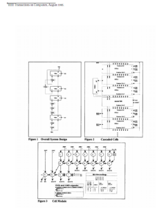
The overall IIR filtering system is modeled by the following difference equation: Y[n] = X[n] + A1 X[n- 1] + A2 X[n-2] + B 1 Y[n- 1] + B2 Y[n-2], where each coefficient (A1,A2,B 1,B2) corresponds to a filtering unit, connected as shown in Figure 1. Within each filtering unit are a series of multiply-accumulate modules (cells) connected in parallel. The magnitude of the input signal X and the computational latency determine the number of multiply-accumulate modules between each pipeline register, as well as the total number of multiply-accumulate modules required within each filtering unit.
In my design, I use a residual function, Zj = 2 (X# Yj + A – Mj- ), j= 1,2,…,n , defined in the j- journal article to facilitate the computation of the result word M. After j iterations, the partial result Mj- is computed, where is the computational latency or delay of the algorithm. Figure 2 shows part of the contents of each filtering unit in my design, illustrating the cascade of multiply-accumulate modules (cells), separated by pipeline registers. Here, successive residuals are seen passing from each cell to the next. Figure 3 shows the multipliers and adders which make up each multiply-accumulate module.
References
- IEEE Transactions on Computers, August 1995.

