Cynthia E. Mills and Dr. R. Steven Turley, Physics and Astronomy
Little is known about the interaction of extreme ultraviolet light (EUV) with materials. This project is a beginning step to filling the information void. My wavelength, 584 Å, is a dominant He I line in the EUV, the 1s 2p to 1s2 transition. The electron gas model predicts that the more electrons a material has the greater its reflectance should be, which implies that U may reflect more than most substances in this region, because of its high atomic number.1 One of the obstacles to research in the EUV is that light is so readily absorbed by everything including air, so all measurements have to be made in vacuum and the signals are generally weak. Another obstacle is the lack of information itself, which complicates sources and detectors.

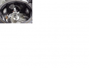
For this project I constructed a multi-angle measurement system inside an existing vacuum chamber. The current assembly is shown in figure 1. The two metal bars coming out from under the rotation stage attach the worm gears on the rotation stages to knobs outside the chamber though a mechanical feedthrough. This is a temporary setup because our first motors died and we are waiting for new motors to come in. This system consists of five computer controlled, stepper motor driven stages and a channeltron detector. Three of these stages are linear to move the sample in the x, y, and z directions. I assembled them from existing track and then designed brackets and plates to attach the motors to the assemliage. The other two stages are rotational. One for the sample, to adjust the incident angle at which the light hits and the other for the detector. Special care was taken in their design because they needed to have a common center, but turn independantly and not be taller than four inches in combined hight. These stages were built especially for this project. I wired each of the motors through a vacuum electrical feedthrough to their drivers and the drivers to the computer. I wrote a LabVIEW program to control the motion of any of the stages by inputing the stage, the direction, and the distance you want. This program is used inside a second program I wrote to automate the entire measurement process, but this second program cannot be used until the new motors are installed in the system.

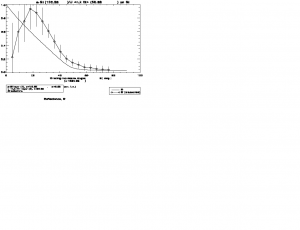
With the vacuum chamber attached to a helium plasma hollow cathode lamp through a monochromator, I measured the reflectance of uranium sputtered onto a silicon wafer and capped with sputtered silicon to prevent oxidation. The resulting data is in figure 2. The low reflectance for shallow angles probably means that the sample was not aligned exactly, because shallow angles are more sensative to a small alignment problem, because the beam is spread out across the surface of the mirror and parts of the beam can miss the mirror. Outside of this region my data shows a higher reflectance than the model predicts. This is unusual, but I have checked for random scattered light coming into the detector, the normalization of the data, and the stablity of the light source that could have caused such a result, but found that none of these problems existed to the necessary extend to acount for the data, leading me to believe this data until another cause is found. My model uses the closest optical constants we have which are about 100 Å away, but no reasonable modifications can also be improved by getting better measurements of the thicknesses of each layer in my sample using xray diffraction.
This is a work in progress, but the measurement equipment I designed and built has already been used to aid four other research projects in my group, and promises to aid many others.2
References
- Squires, Matthew B. On Determining the Optical Constants of Sputtered U and a-Si at 304Å and 584Å. Senior Thesis. Brigham Young University. 1999.
- I want to acknowledge the help of Matthew Squires, Cort Johnson, Michael Hales, Jason Flint, and Jason Rowland on this project.
