Aaron Bennett and Dr. Dallin Durfee, Physics
I will discuss a high speed, low noise homodyne photo-detector. This detector will be used to better implement laser locking techniques, such as the Pound-Drever-Hall Method, that use lock-in detection. A basic explanation of the Pound-Drever-Hall method is presented in my proposal. In this report, I will discuss aspects of the detector which allow it to operate with lower noise and over a higher bandwidth than other comparable devices. I will focus this report on the difficulties that I encountered while designing this detector and the solutions that I found.
As discussed in my proposal, the purpose of my project is to create a device that implements an extremely sensitive laser frequency lock. The device itself detects a rapidly oscillating (with a rate of between ten million and one hundred million oscillations per second) light signal with a photodiode, transforms the photodiode output current into a voltage, amplifies that voltage, and finally mixes (electronically multiplying the two signals together) that voltage with another voltage oscillating at the same frequency. The mixer output (the result of multiplying the two signals together) is used as an error signal in a feedback loop that restores the laser to a desired frequency.
Currently, there is not a prepackaged commercially available device similar to the one that I designed. However, it is possible to make a circuit similar to mine with commercially available parts, but doing so has two main downsides. First, the performance of commercially available alternatives is lacking compared to my circuit. A commercial alternative would involve purchasing all of the same parts that I used separately and linking them together with BNC cables (i.e. buying a high-speed photodiode and linking that to an amplifier which is connected to a mixer, etc.). Linking these components in this manner would introduce significantly more noise than my circuit does because the components in my circuit are all placed close together on the same board. Not only would the noise be negatively affected, but linking through BNC cables to different components may also negatively affect the speed of the circuit. Overall, my circuit out performs a commercial one because mine is quieter and runs faster. The second downside to a commercial alternative is cost. My board is relatively cheap to produce and is relatively simple to assemble (assembling and testing a board may take a couple of hours, but not much longer). The commercial alternative would be somewhat simpler to assemble (requiring one to simply connect BNC cables between the components) but would be very expensive (especially considering the high bandwidth these parts would need).
For my detector, I had two main goals, both of which were particularly challenging. First, I wanted my detector to be shot noise limited for a milliwatt laser. Because my detector will be used in an ultra stable laser lock, it is essential for it to be extremely quiet. Any unnecessary noise will destabilize the lock and potentially cause the entire experiment to break down. Second, I wanted to be able to detect and amplify signals that oscillate as fast as 100 MHz.
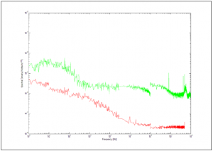
The main thing that I did to reduce the noise in my detector was to find amplifiers that introduced extremely small amounts of noise. The figure on the right shows the spectral noise density for my amplifier (the red line represents the noise floor and the green line is the noise produced by my detectore). The actual noise for my circuit was a little more than the theoretical noise that I calculated (not shown in the figure) but is still impressively low.

Designing a detector with such large bandwidth proved to be a significant challenge. First, I had to find amplifiers that had a large bandwidth without introducing significant amounts of noise. It soon became clear that a bandwidth of 100 MHz was not an entirely realistic goal. With the fastest amplifiers that I could find, the bandwidth for my detector as a whole theoretically should be around 60 or 70 MHz. Next, I needed to ensure that the physical layout of the printed circuit board did not negatively affect the speed of the circuit. Most importantly, I needed to design a board that did not introduce stray inductance and stray capacitance into the circuit. To reduce stray inductance, I kept all of the components involved in amplifying the high speed signal on one side of the board (thus removing any unnecessary loops that will introduce stray inductance and slow the circuit). Also, I chose electronics that allowed me to minimize the size of the remaining loops on the board (also reducing stray inductance). To minimize stray capacitance, I needed a good understanding of what factors contribute to stray capacitance. Because I was unable to find any literature on the subject, I wrote a computer program that models stray capacitance in different circuit board layouts. Using this program, I found that the most important factor for reducing stray capacitance is the proximity of ground planes to signal lines (the closer the ground plane the more the capacitance). Consequently, I cleared all of the ground planes around any lines that carry high speed signals (including the ground planes on the bottom of the board).
I have not yet made any conclusive findings about the bandwidth of my detector. There are two things that I have yet to resolve. First, I have been unable to determine whether a particularly large output at about 7 MHz is a result of a resonance in the circuit. If it is a resonance, the output appears to be fairly flat out to about 45 or 50 MHz and rolls off to 3db around 60 or 65 MHz. If it is not a resonance, the circuit rolls off much faster than expected for some unknown reason. The second unresolved issue is that the detector output at all frequencies is about half as large as theoretically calculated (for some unapparent reason).
