Thomas Knotts, Chemical Engineering
1 Background
The overall goal of this project was to provide new theories and models that describe DNA hybridization on surfaces on a fundamental level for improved application and design of microarrays. Microarrays work on the principle of DNA hybridization, and can be used to identify the identity or abundance of genes present in a sample of interest. They have the potential to revolutionize many fields including medicine, genomics, and defense, but improved engineering of the technology is needed before microarrays can achieve their promise in these areas.
One of the barriers preventing optimization of the technology is that fairly little is known about how the hybridization process occurs on surfaces. Hybridization is the fundamental process enabling microarray technology, so the devices can only be as reliable as this process is efficient. However, hybridization on microarray surfaces occurs in an environment that is significantly different than the normal cellular context. As such, models are needed that describe the natural process as well as the influence of outside factors (such as a surface). This project provided fundamental understanding of microarray behavior beyond what has been known previously.
2 Results
Previous efforts of modeling DNA hybridization focused on the ideal case where one DNA molecule was attached to the surface (the probe) at one end and one was free in solution (the target). The results described below explain how this research moved modelling beyond the ideal case to more realistic systems. Two efforts are described. The first models the probe molecule tethered to the surface at multiple locations which represents entanglements that can occur in real microarrays. The second models multiple probes on the surface.
2.1 Probe Tethering Configurations
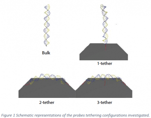
As previously mentioned, previous work featured simulations where the probe strand is attached to the surface at only one end. The present work models the effects of a strand being adsorbed or bound to the surface at more than one location or held near the surface by tangling with other probes. Simulations were done with one, two, and three tethers. For the one‐tether case, the probe is bound to the surface at one end of the molecule. For the two‐tether case, the molecule is bound to the surface at both ends. The three‐tether case has one additional bond attachment point in the middle of the molecule. These cases are illustrated in Figure 1 .
In single tether cases, the hybridized duplex stays near perpendicular to the surface, so no large strain is imposed on the tether. In the 2‐tether cases when both tethers are attached to the surface some strain is introduced into the tethers. The hybridized pair is also held in a mildly strained position, which is a significant and accurate reproduction of conditions that would be seen in situ.
The single tether case shows the specific effects on hybridization caused by the presence of a surface. Parallel alignment to the surface would likely be caused by tangling with another probe or non‐specific binding to the surface, simulating this with an additional tether allows the effects of the surface to be viewed separately from the effects of the second probe. Similarly, 3‐tethers on the probe strand further restrict the mobility of the probe.
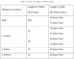
As described in Table 1 below, simulations were performed with 36 base pair strands with 1, 2, and 3‐ tethers. The 1 tether case was simulated with tethers of 15 links and 30 links, all other cases with 36 base pairs were performed with 15 links. Simulations with 51 base pair strands were performed with 1 tether with 15 and 30 links.
2.1.1 1 Tether Results
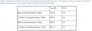
Table 2 contains the melting temperatures of the duplexes of 36 and 51 base pairs in the bulk and tethered to the surface at one location. The melting temperature was lowest for the 36 base pair duplex in the bulk and highest for the 51 base pair duplex on the surface. For the 36 base pair cases, the tethered case has a melting temperature that is ~36K higher than the bulk case. For the 51 base pair cases, the tethered case is only 7K higher than the bulk case.
These data indicate that a single tether increases the stability of probe strands compared to hybridization in the bulk solution. This is in agreement with previous studies performed on 21 base pair DNA strands22. Comparing the 36 and 51 base pair strands shows an interesting trend. The absolute difference in stability between the bulk cases and the corresponding single tether cases is much smaller for the 51 base pair case than the 36 base pair case. In both cases, tethering the DNA to the surface increases stability, but the effect is greater for the 36 base pair case. Moreover, the increase in melting temperature of the 51 base pair case over the bulk is likely not statistically significant. The reason for this difference is likely the increased flexibility of the longer DNA strand: the portion farthest from the surface has more of an ability to move as would a strand in the bulk and “feels” less of the surface effects.
2.1.2 2 Tether Results
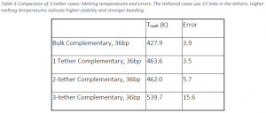
Table 3 compares the results of studies with 2‐tethers to bulk and single tether cases, as well as the 3‐ tether case which will be discussed later. The 2‐tether case has a melting temperature that is ~34K higher than the bulk case and 1.6K lower than the 1 tether case. The difference between the melting temperatures of the 1 and 2‐tether cases is within statistical error suggesting that increasing the number of tethers to two does not drastically affect stability of the duplex.
Simulations with a tether at both ends of the probe strand yielded unexpected results. It was theorized before the simulations were performed that the close proximity to the surface and additional restriction to mobility would destabilize hybridization. Instead, the results of the 2‐tether studies indicate that both 1 and 2 tethers increase the stability of the duplex equally. The additional restriction in mobility and more direct interaction with the surface did not appreciably change the overall stability. This lack of change could be caused multiple competing effects. Therefore, varied tether length and a 3‐ther case were also tested in order to isolate the effects of features such as proximity to the surface and restriction of mobility.
2.1.3 3 Tether Results
Table 3 contains the melting temperature of tethering the 36 bp strand to the surface using 3‐thethers and compares these values to the bulk, 1‐tether, and 2‐tether cases. The data show that adding another tether drastically increases the melting temperature of the surface‐bound, DNA duplex. The 3‐tether case is approximately 112K higher than the bulk value, 76K higher than one tether, and 78K higher than 2‐ tethers. The error for the three‐tether case is much higher than the other treatments, but the difference remains still statistically significant.
2.1.4 Tether Length Effects
Tether lengths used in the majority of the simulations were 15 segments long. In order to determine how tether length affected the stability, studies were also performed with tethers of 30 segments. The effect of tether length on stability has been studied previously in the context of single tethers. Such work is repeated here using the systems of this study to help clarify the phenomena explained above, particularly the role that motion restriction plays in stability. Longer tethers were expected to reduce hybridization stability compared to shorter tethers, bringing the melting temperatures closer to bulk values.
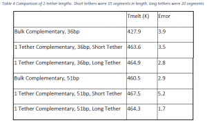
Table 4 shows the comparison of the melting temperatures for the 36 and 51 base pair cases with long and short tethers. The melting temperatures for the longer tethers are statistically identical to that of the short tether. The long tether in the 36 base pair case is only 1.3K higher in melting temperature than the short tether case. In the 51 base pair case, the melting temperature of the longer tether case is 3.2K lower than the short tether case.
Based on previous research illustrating the stabilizing effect of the surface, the expectation was that longer tethers would distance the strands from the surface and behave more like bulk strands. Instead, within the experimental errors, the differences between long and short tether cases are insignificant. This result suggests that the proximity to the surface isn’t as important as the mere presence of the surface and its ability to keep the target and probe closer together than they would be in the bulk.
Discussion about Tether Configurations
This study confirmed that tethering DNA to a surface with one tether increases the stability of a duplex compared to the bulk and that adding more tethers amplified the stabilization. The increase in melting temperature was approximately the same in cases where only one end was tethered to the surface or if both ends were tethered but adding a third tether dramatically increased the melting temperature. These results suggest that simulations of microarrays accurately predict behavior with only a single tether if the degree of interaction with the surface is known to be low. However, in cases of very high degrees of interaction with the surface, the highly constrained mobility with respect to the surface is expected to alter behavior and thermodynamics considerably.
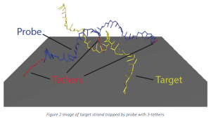
In the 3‐tether case complete melting is inhibited by the target becoming trapped between the highly constrained probe and the surface. This effectively stabilized the hybridization to a much greater degree than simple attachment to a surface by one or 2‐tethers. The variability in the measured melting temperature for the 3‐tether case was very high, suggesting that this high degree of interaction with the surface should be avoided to gather accurate data from DNA microarrays.
Three‐tether configurations of DNA were also expected initially to weaken hybridization, especially due to the much more severe restriction in mobility caused by the presence of the tether attached to the center of the probe strand. The lengths of the tethers are the same as in the two‐tether case, so any changes in stability are not related to the distance of the probe from the surface but to the restricted configuration of the surface.
Snapshots taken from the simulation with 3‐tethers help explain the change in stability. Unspecified reference source shows a snapshot at 300 K. Notice that the additional restriction in motion of the hybridized pair made it common for the target strand of DNA to become trapped between the probe strand and the surface even when melting was almost complete. The restricted physical orientation of the probe with the surface prevents melting from occurring as easily as in the bulk case. These results run counter to the hypothesis that restriction of mobility and introduction of additional strain would have destabilizing effect on hybridization. It appears that the driving force of the stabilization is the ability of the surface to restrict the movement of the target away from the probe, keeping of the target near the probe once it is there.
2.2 Multiple Probes
The purpose of this study was to move away from the ideal one‐probe/one‐target model to more realistic systems by examining the hybridization of a target to a probe when multiple probes are found on the surface. The hypothesis tested was that due to crowding effects among surface probes, surface hybridization in the presence of multiple probes is less stable than hybridization of a single probe to a single target. This hypothesis was tested by calculating PMF’s for the control and various treatments. The PMF is the reversible work or free energy needed to move the system along the reaction coordinate defined as the distance between the strands.
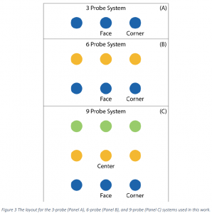
Four different configurations of probes were used: 1 probe (the control), 3 probes, 6 probes, and 9 probes. All probes were placed in a straight line for the 3‐probe case (See Panel A of Figure 3). The 6‐ probe case was created using two rows of the 3‐probe case (Panel B), and the 9‐probe case consists of three rows of the 3‐probe case (Panel C). For the 9‐probe case, the target can hybridize to three different types of probes: center, face, and corner. The center type is in the middle of the group and has neighboring probe molecules in each direction in the lateral plane (360° of neighbors). The face probe is found at the edge of the group and has approximately 180° of neighbors and 180° of lateral access to the bulk. The corner probe is also found at the edge of the group and has 90° of neighbors and 270° for bulk access. It was expected that the most steric hindrance occurs for hybridization at the center probe and the least steric hindrance is found at the corner probe. The naming conventions in the 6‐ and 3‐probe systems are maintained to be consistent with the 9‐probe system. Only face and corner probe types are found in these systems as indicated in the figure.
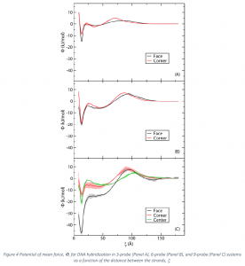
Figure 4 depicts the PMF’s for hybridization of the target to probes in the 3, 6, and 9‐probe configurations. Results for hybridization to all types of probes (face and corner for the 3 and 6‐probe configurations and face, corner, and center for the 9‐probe configuration) are shown. Each configuration is discussed below.
Panel A of Figure 4 shows the PMF for hybridization of the target to a probe in the 3‐probe system. The black line represents the scenario in which the target strand is hybridized to the face probe, and the red line indicates the scenario when the target strand is hybridized to one of the edge locations (corner). The plot shows that the most stable state for both locations occurs at ξ=13.5 Å where the target and the probe strands are fully hybridized. Overall, the face location produces a more stable duplex. The difference in the changes in free energies of hybridization between the face and corner probes is ![]()
A stable intermediate is found in both the corner and face situations for the 3‐probe system. (See Panel A). This minimum occurs at approximately 35 Å for the corner case and 40 Å for the face case. The corner intermediate appears to be slightly more stable. Specifically, the barrier to escape from the stable intermediate and proceed to the properly hybridized state (the escape barrier) is 2.6 kJ/mol for the corner while that for the face is 1.5 kJ/mol for a difference of 1.1 kJ/mol. Finally, both situations also encounter an entropic barrier as the strands approach each other from far distances. The barrier reaches a maximum of 4.8 kJ/mol at approximately 60 Å in the corner case and a value of 2.8 kJ/mol at 70 Å in the face case for a difference of 2.0 kJ/mol. In short, the energy landscape for hybridization to a face probe is flatter than that for the corner probe. Panel B of Figure 4 shows the PMF for hybridization of the target to a probe in the 6‐probe system. The black line represents the scenario in which the target hybridizes to the face location while the red line represents the case when the target hybridizes to one of the corner locations. As was seen in the 3‐probe case, the face scenario produces a more stable duplex. For the face probe, the change in free energy of hybridization is ![]() while that of the corner is
while that of the corner is ![]() for a difference of
for a difference of ![]() The errors suggest that this difference is significant, but it is of lesser magnitude than the 3‐probe case. In other words, the difference in the overall stability of the duplex between the face and corner locations is less in the 6‐ probe case than in the 3‐probe case.
The errors suggest that this difference is significant, but it is of lesser magnitude than the 3‐probe case. In other words, the difference in the overall stability of the duplex between the face and corner locations is less in the 6‐ probe case than in the 3‐probe case.
The 6‐probe escape and entropic barriers are larger than the corresponding 3‐probe values (See Panel B of Figure 4). They also follow the pattern seen in the 3‐probe case in that hybridization to a corner probe produces higher escape and entropic barriers than hybridization to a face probe. Specifically, the escape barrier for the corner probe is 2.0 kJ/mol higher and the entropic barrier is 0.6 kJ/mol higher than the corresponding values for the face probe for the 6‐probe system. In short, the PMF for the face probe is slightly flatter than that for the corner probe for the 6‐probe system, and overall the landscape for the 6‐ probe system is more rugged than the 3‐probe case.
Panel C of Figure 4 shows the PMF for hybridization of the target to a probe in the 9‐probe system. The black line represents the scenario where the target is hybridized to the face location, the red line indicates the case where the target is hybridized to the corner location, and the green line represents the case where the target is hybridized to the center location. The face location is the most stable overall with ![]()
One striking feature seen in the 9‐probe case that is not found in the 3 or 6‐probe systems is the absence of a stable intermediate and accompanying escape barrier for the face case. The corner case has an escape barrier but its magnitude is only 1.7 kJ/mol. This is less than the corresponding value in both the 3 and 6‐probe systems. The entropic barrier for this probe is 8.0 kJ/mol which is the largest of all the cases studied. The center location of the 9‐probe system has the highest escape barrier at 4.4 kJ/mol but the entropic barrier for this system is the lowest of all the 9‐probe values. Specifically, the values of the entropic barrier for the 9‐probe system are ![]()
3 Evaluation of how well the academic objectives of the proposal were met.
As evidenced by the results found in Section 2, the academic objectives of the proposal were met very well. Recall that the main goal of the work was to provide new theories and models that describe DNA hybridization on surfaces on a fundamental level for improved application and design of microarrays. This was done by modelling DNA hybridization on surfaces in a manner that has not been done previously. Below, the manner in which this new modelling can improve microarray design is discussed. Note that both areas of research have been prepared for publication in the Journal of Chemical Physics. The results of Section 2.1 will be submitted within the next two months. The results of Section 2.2 have already been submitted and accepted and will appear in the January 12, 2015 edition of the journal.
3.1 Multiple Tether Locations and Improved Microarray Design.
Microarrays are designed so that each probe target complex across the entire chip melts at approximately the same temperature. This is done using a computer algorithm that takes the sequence of the gene of interest and looks for sections of the gene which would produce a duplex with a certain melting temperature. The melting temperature of these potential probe/target complexes are predicted using fairly accurate correlations which take into account the sequence, salt concentration, and other factors that has been shown to affect double stranded DNA stability. However, these correlations were developed based on experimental data taken in the bulk. One key recommendation from these results for microarrays is that to ensure consistent behavior of microarrays, the degree of interaction with the surface should be taken into account when selecting probes as there is a large difference between the melting temperatures of a probe‐target complex tethered at one location on the surface and one that has more complex surface interaction.
3.2 Multiple Probe and Improved Microarray Design
As was mentioned in Section 3.1, one of the main concerns when designing probes is to ensure that the duplex melting temperatures across the entire chip are equal. Current protocols to accomplish this rely on melting temperature estimation techniques that were developed using bulk experimental data and do not take into account the probe packing effects elucidated in this work. Specifically, the protocols do not take into account that a probe/target pair with the same sequence will have different stabilities depending on its location in the probe pack.
This goal of uniform melting temperatures across the entire chip has principally been applied to different probe sequences found on the same chip‐‐specifically that the probes screening for gene A at location 1 should have the same melting temperature as those screening for gene B at location 2. Conventional wisdom held that identically‐sequenced probes at two different locations would have the same melting temperature. However, the results of this research call this assumption into question. The data reveal that stability (and consequently melting temperatures) for identically‐sequenced pairs can differ among probes in the same pack due to the asymmetry of attractions and the crowding that interior vs exterior probes experience.
Due to this intra‐pack variability, achieving the sought‐after uniformity in melting temperature across the chip is likely difficult using current microarray designs. Moreover, in regards to proximity, there are probes that are often ineffective in terms of hybridization due to their limited accessibility. One possible way to improve both the uniformity and efficacy of probes is to design the spots on the microarray in a way that eliminates or reduces the number of “interior” probes. Multiple ways to do this can be imagined. For example, probes could be arranged in lines rather than circular spots or donut‐shaped spots could be used. While these represent radical departures from current standards, the results in this study suggest that such could improve microarray performance.
4 List of Students Who Participated and What Academic Deliverables They Have Produced or It Is Anticipated They Will Produce
The original proposal asked for one graduate student supported at ½ time and two undergraduate researchers supported at ¼ time. This was what was done with the funds from the grant. Table 5 lists the students, their level (graduate/undergraduate), and their current of future positions.
The works delivered by each student are found in Table 6.
5 Evaluation of the Mentoring Environment
The mentoring environment I was able to create with the funds from the MEG was very successful at creating a valuable learning experience for each involved student. The research performed in my lab requires extensive training and a commitment to helping the students succeed. As evidenced by the data found in Section 4, this mentoring was successful.
Each student involved in the research has or is in the process of delivering a published manuscript based on his research. The paper by Ryan Welling has already been accepted and is in press. Kyle Pratt has already written his manuscript and we are on the 4th revision. Ben Lindsay is in the process of writing his manuscript and has a rough draft. It may seem like Ben is a little behind, but his project was much more difficult than those undertaken by Kyle and Ryan. Despite the timing, the results are quite phenomenal, and I have no doubt that they will be published.
Evidence of the success of the mentoring environment is also found in the present or future plans of each student. Kyle was hired by Intel Corporation even though his research was not in semiconductors or electrical engineering. This attests to the quality of his work. Benjamin Lindsay is currently a graduate student at the University of Pennsylvania, one of the premier graduate schools in the nation. Finally, Ryan Welling was secured a position in a very competitive company. In short, the mentoring environment has helped these students produce excellent work, prepare for the future, gain confidence in their abilities, produce deliverables on the national stage, secure highly‐desirable employment and graduate positions.
6 How the Budget Was Spent
All of the funds supported the wages of the students involved. I leveraged the MEG funds with funds from the department and other grants I have to send the students to conferences.

