Andrew Sieler and Dr. Stephen Schultz, Electrical Engineering
Main Text
The use of optical fiber as a sensing instrument has become an important application in the optics field. Due to previous research conducted here at BYU1 it is now possible to fabricate Surface Relief Fiber Bragg Gratings, SR-FBGs, which can be used as a temperature or strain sensing instrument. This sensor is lightweight and immune to electromagnetic interference because of the inherent attributes associated with optical fiber. The type of FBG I wish to research, the FP-FBG, will be much more sensitive than a standard SR-FBG. Another quality of optical sensors is the fact that they are so compact they can be embedded into structures and used to sense changes in the structure’s integrity. A potential application of Short Surface Relief Fabry-Perot Fiber Bragg Gratings, FP-FBG, is to install them in key points during the building process of any structure such as a bridge. Once the structure is completed a measurement may be taken at the key areas to give a baseline reading. Periodic measurements can be taken and with the data taken it can be determined if the structural integrity has been maintained in that key area or if repairs are necessary. This is just an example of one of the many different uses of this sensor.
The first step to achieving the goal of a FP-FBG sensor is through fabrication, which so far has proven to be the most difficult and complicated step. This is as far as I have gotten with my research. I have not started testing the FP-FBG yet. There are close to a hundred steps involved in making the FP-FBG. A portion of this work was already done previously for the fabrication of the standard SR-FBG sensor as mentioned previously. However, following a list of procedural steps of instructions to get a desired result is much more difficult than one would imagine. I had a list of all the major steps involved in the fabrication of an SR-FBG, but sometimes getting from step one to step two involved a myriad of other little steps and techniques that would be required. This happened quite often while first trying to just duplicate the fabrication of the standard SR-FBG. An example of this is when I had to coat a portion of the fiber with photoresist in the Cleanroom Facility in the Clyde Building. The step mentioned taping the fiber to a silicon wafer. It sounded like a simple idea at first, but it eventually became clear that a more precise way was needed. First it needed to be done in such a way that when I removed fiber from the wafer, the fiber didn’t break as the fiber has undergone various processes by this step and is more fragile. So a colleague of mine developed a tape loop where the fiber would be securely fastened onto the wafer in such a way that the adhesive part of the tape was not touching the fiber at all, thus removing all risk of breaking the fiber. Another necessary item was for the fiber to be taped onto the wafer in such a way that the photoresist would be applied evenly and this too needed to be accounted for with separate pieces of tape to hold down the correct section of the optical fiber.
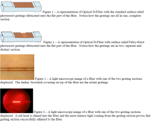
The main difference between standard SR-FBG and the FP-FBG is found in the exposure process of the photoresist. See Figure 1 and 2 for the physical difference between the two type of FBG sensors. First off there has to be a special mask made to create the two separate grating sections for the FP-FBG. These gratings section are 500mm in length and so a special computer aided design was needed to be put onto a special glass mask. This mask was then used with an ultra violet lamp to do a pre-exposure step which allowed for an initial pattern to be put onto the photoresist. The next step in the exposure process involved using an argon laser with an ultra violet output to expose another pattern onto the photoresist. There was an equation formulated to determine the correct amount of time needed to expose the photoresist, but with the new FP-FBG a new equation needed to be formulated. Once I determined this new formula the rest of the fabrication was relatively simple.
The main difficulty in the fabrication of FP-FBGs is found in the yield. Very few of the all the fibers I have fabricated end up with a successful grating section that can be used as a sensor. Figure 3 and 4 show an example of a fiber that was successfully made. In the future it is my desire to develop a better, more repeatable fabrication process so that the yield of successful fibers may be greater.

