Janette Fernelius and Dr. Larry L. Howell, Mechanical Engineering
Introduction
Materials are selected for design applications based on weight, flexibility, thickness, compatibility with the use environment, and the availability of the material. These characteristics place limitations on design that are difficult to satisfy with conventional methods and mate- rials in some circumstances. Origami can be used to modify the flexibility, bending stiffness, and strength of a material, and so engineers are turning to origami to meet their design needs. One class of origami under investigation is origami tessellations. Origami tessellations are made from repeated fold patterns called unit cells, and are used in deployable structures. The capability of mathematically modeling the behavior of origami tessellations during deployment will save time and money in the design and test stages of product development. When a material is stretched in one direction, it normally compresses in another. This behavior is mathematically modeled using Poisson’s ratio. Using origami, one can modify a material’s structural behavior to expand in one direction as it is pulled in another. This research analyzed the Poisson’s ratio of five origami tessellations. Because this relationship can be established for all tessellation patterns, engineers will be able to predict the Poisson’s ratio of any fold, and can select fold patterns based on their specific needs.
Methodology

The method used to determine Poisson’s Ratio is shown using the Waterbomb base tessellation. First, the selected tessellation pattern was reduced to the unit cell (see Figure 1). Properly defining “length” and “width” of an expanding and collapsing structure can be difficult because the lines are defined by points, rather than edges. It is critical that the lines created by these points are perpendicular regardless of the deployment angle. Three points are selected: two define the length and two define the width, with one point being used in both length and width. Once length and width are defined, constant lengths and angles are labeled, and a single independent variable, called the deployment angle, is selected. In this example, the deployment angle is θ, which is the angle at the ”crown” of the fold. Variable R is defined as the distance between the first and second points, as defined in Figure 1, and L is defined as the length of the side of one square in the pattern. Once R is determined, one can use trigonometry to calculate for w and l.

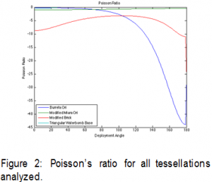
Because w = l, dw = dl, and Poisson’s Ratio, defined as ![]() for the Waterbomb base tessallation is -1. The four other origami tessellations were analyzed using the same process. The results are shown in the figure below.
for the Waterbomb base tessallation is -1. The four other origami tessellations were analyzed using the same process. The results are shown in the figure below.
Results and Discussion

All of the tessellation patterns produce a negative Poisson’s ratio. This means that as the origami is stretched in one direction, the tessellation expands in the other direction. Traditional materials have Poisson’s ratios between -1 and 0.5. However, with the analyzed patterns, the negative Poisson’s ratio can be as great as -44. Each of the ratios are dependent on deployment angle, and varies during the deployment process. Because the equations quantify the motion of the origami at any stage of deployment, the engineers can use origami tessellations for deployable structures to exactly meet the design specifications.
Conclusion
Origami tessellations can be used to resolve design problems by altering structural proper- ties such as Poisson’s ratio. Poisson’s ratio can be mathematically modeled for all tessellations. Equations can be calculated using geometry and kinematic principles. Understanding Poisson’s ratio will save time and money in the test and development stages by removing unnecessary prototyping. Engineers can select patterns based on design specifications, and can improve structural properties by modifying the shape of the material.
