
Bryce McEwen and Dr. Steven Gorrell, Mechanical Engineering
Main Text
With ever increasing concerns about the production of greenhouse gases from burning fossil fuels, more and more emphasis is being placed on researching and developing alternative and renewable energy resources. One renewable energy source that has the potential to compete with conventional fossil fuels, is wind energy. In order for wind energy to be competitive, it is necessary to make improvements in both aerodynamic and structural properties of wind turbines.
To investigate possible improvements in aerodynamic efficiency in small wind turbine blades, I used a statistical design of experiments, which is a statistical method where the significance of multiple combinations of variables is determined from experiments performed only on key variable combinations. In my research, the key variables are geometric parameters, which define the shape of a small wind turbine blade. FLUENT, a computational fluid dynamics (CFD) software package was used to calculate the ratio of lift to drag on the different sets of blade geometries. I used the design of experiments to determine what geometric parameters would provide the optimal lift-to-drag ratio.
The main geometric parameters I chose to define the blade shapes were: transition point location, pitch axis, and taper ratio. These parameters were based off of a paper on a similar parametric study1. Many wind turbine blades consist of at least two standardized airfoil profiles. The transition point is defined as the point along the blade at which the transition is made from one profile to the other. Pitch axis is usually given as a percentage of the length of an airfoil profile, known as the chord length, and is an axis along which all profiles are aligned. Figure 1 shows a cross section of a blade with a pitch axis at 30% of the chord. Taper ratio is the ratio of the chord length of the root profile to the chord length of the tip profile (CR/CT).
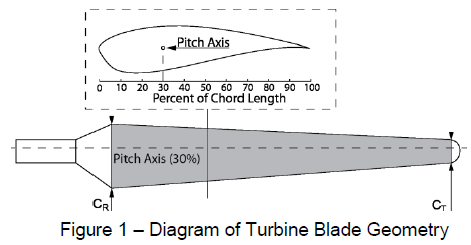
In literature I found that standard profiles created by the National Renewable Energy Labs were created specifically for small wind turbines2, and these are the profiles I used to define the blade geometries. The shaded section of the blade shown in Figure 1 represents the section of the blade that I analyzed, and does not include the hub and tip geometries. Creating the blades in a CAD system presented problems when I imported them into the CFD meshing program. I overcame these problems by creating a computer script to generate commands for constructing blade geometries in the meshing program itself, given values for the three parameters. I imported meshes into FLUENT, where I specified a wind speed of 34 m/s with a non-rotating blade section. The solution was run to 1500 iterations to find the lift-to-drag ratios for each of the blade designs, the results are shown below in Table 1.
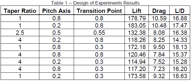
The maximum lift-to-drag ratio occurred at 20% pitch axis, 30% transition point, and a taper ratio of 1. I used Minitab, a statistical software package, to analyze the design of experiments to predict what combination of variables would yield the maximum lift-to-drag ratio. The combination of variables that predicts the maximum lift-to-drag ratio is the same set that yielded the maximum in the results. The only variable that shows statistical significance is taper ratio.
Originally I planned to see how thickening or blunting the trailing edge of the blade (known as flatbacking) would affect performance, but through research, I learned that the purpose of flatbacking is to increase structural integrity and reduce noise3. Since small wind turbines operate at lower speeds, they are not subject to same structural and noise issues as larger ones, and hence I decided not to include flatbacks. I was unable to obtain access to a 3d scanner in order to base my blade geometries off of the Wind Energy Club wind turbine blades as I had originally planned, and Southwest Windpower did not provide me with the geometries.
For future work, I would suggest that the CFD solution be verified to make sure that all of the conditions and solvers were set up properly. The simulation could be made more representative of an actual wind turbine blade by including the tip and hub geometries and including rotation. If rotation were to be included, it would be useful to include an additional geometrical parameter, twist distribution, in order to better optimize the blades. Since this is a comparative study, the actual lift-to-drag ratios are not crucial, but an experimental validation of the results would be necessary if actual prototypes were being considered for production. A more rigorous analysis would also compare aerodynamic performance over a range of wind speeds, instead of at a set wind speed of 34 m/s.
References
- Giguère, P., and M. S. Selig. Design of a Tapered and Twisted Blade for the NREL Combined Experiment Rotor. Rep. no. NREL/SR-500-26173. Golden, CO: National Renewable Energy Laboratory, 1999. Mar.-Apr. 1999. Web. <http://wind.nrel.gov/amestest/BladeDesign.pdf>.
- Somers,D.M. The S822 and S823 Airfoil. Rep. no. NREL/SR-500-36342. Golden, CO: National Renewable Energy Laboratory, 1993. Dec. 1993. Web.<http://wind.nrel.gov/airfoils/Documents/S822,S823_Design.pdf>.
- D.E. Berg and J.R. Zayas, Aerodynamic and Aeroacoustic Properties of Flatback Airfoils, 46th AIAA Aerospace Sciences Meeting and Exhibit, 27th ASME Wind Energy Symposium, Reno, Nevada (January 2008).