David Landry and Dr. David Allred, Physics Department, College of Physical & Mathematical Sciences
Microelectromechanical systems (MEMS) are commonly used to build sensors for consumer products such as game console controllers1 and smart phones2. These sensors use piezoelectric materials and are wired directly into a larger electronic system. Because of their use case, these sensors are designed to operate near room temperature. The goal of this project was to help create a remotely detected MEMS accelerometer capable of operating in high temperature and high acceleration environments.
As originally envisioned, my part was to model and create the sensor and reader circuits, where the sensor circuit contains the MEMS sensor and any components needed to transmit the state of the sensor, and the reader consists of an antenna and any components needed to receive and decode the state of the sensor. As I learned more background about antennas and more about antenna-specific research on campus in the Electrical Engineering department, it was decided that it would make more sense to make use of an existing test setup for the receiver-side, and integrate the sensor directly to an antenna.
The system uses the principal of back-scatter to query the devices3. A method for wirelessly reading unpowered sensors was presented at the Electronic Components and Technology Conference in 2007 based on work done at Sandia4, showing that the backscatter can be applied to more generally find the impedance of a remote, wireless sensor. As currently envisioned, any sensor to be used is integrated with a loop antenna. The state of the sensor alters the overall impedance of the system. Since the resonant frequency of an antenna can be altered by changing the impedance seen by the antenna5, when the sensor alters the system impedance, the shift in resonant frequency can be seen by querying the sensor antenna with a spectrum of frequencies and viewing which frequencies backscatter strongest.
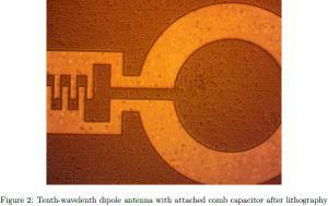
In order to test this, we designed a set of circuits comprised of a finger or comb capacitor attached to an antenna and created a mask for lithography. This would allow us to characterize the resonant frequency of the antenna with a fixed impedance and act as a proof of concept for the wireless sensor. We included three variations on the antenna: a dipole antenna, a wavelength loop antenna, and a tenth-wavelength loop antenna. Dipole antenna are desirable because they are easily modeled. However, a loop antenna would be more likely to help hold the sensor together if we lift the sensor off the substrate. According to a source I found, tenth-wavelength loop antenna have a similar far-field radiation pattern to dipole antenna, so we decided to include it as a third variation.
Unfortunately, we had some major set backs in actually fabricating the devices. The machine for depositing iron, a precursor to carbon nanotube (CNT) growth, was out of order for a while. When all the needed equipment was functional again, first we had problems getting the lithography right, then we had difficulties with the new iron deposition system. Currently, we have samples that are about half fabricated. As soon as we finish fabrication, we will lift the devices off the substrate, place them on an electrically neutral surface, and characterize the resonant frequency. Future work to be done includes replacing the static comb capacitor with a variable comb capacitor (one type of accelerometer), possibly testing other types of MEMS sensors, fabrication using high-temperature material, and characterization at high temperatures.
References
- Hintze, Christine. “MEMS Sensors Breath Life Into Wii Controller.” Electronic Design. 2006 May 25. <http:// electronicdesign.com/article/components/mems-sensors-breathe-life-into-wii-controller12695.aspx>
- Bouchaud, Jeremie. “Consumer and Cell Phone MEMS to Generate $2 Billion in 2011.” 2011 January 31. <http://www. isuppli.com/MEMS-and-Sensors/MarketWatch/Pages/Consumer-and-Cell-Phone-MEMS-to-Generate-$2-Billion-in-2011. aspx>
- A well documented phenomena, backscatter is used in radar ranging for gauging the size and distance of macroscopic objects. It is also used for querying passive RFID tags (used for product tracking, transportation and logistics, passports, credit cards, etc).
- Brocato, R.W.; Wouters, G.A.; Heller, E.; Blaich, J.; Palmer, D.W.; , “Re-configurable Completely Unpowered Wireless Sensors,” Electronic Components and Technology Conference, 2007. ECTC ’07. Proceedings. 57th , vol., no., pp.179-183, May 29 2007-June 1 2007 URL: http://ieeexplore.ieee.org/stamp/stamp.jsp?tp=&arnumber=4249881&isnumber=4249838
- This principal is used by hobbyists to tune homemade ham and CB radio antennas.


