
Michael Tree and Dr. Scott Thomson, Department of Mechanical Engineering
Introduction
Operation of existing micro air vehicles (small, unmanned aircraft, with a maximum size of 6 inches or less, also known as MAVs) is difficult in urban areas. Most MAVs use a fixed-wing design that is unsuitable for high maneuverability, thus limiting their potential usefulness.
Nature presents flapping flight as a promising solution to this problem. Through the use of flapping flight, birds are highly maneuverable. The variability in flapping pattern of a bird, for example, allows birds to react to varying flow patterns and avoid obstacles. It is therefore believed that flapping flight MAVs would produce similar maneuverability advantages.
While fixed-wing aerodynamics is relatively well understood, there is much to be learned about the aerodynamics of flapping-wing flight. The research conducted explored aerodynamic principles and phenomena associated with flapping flight. In order to adequately study flapping flight the research included the following major components:
- Construction of a robotic mechanism capable of generating a wide range of flapping motions
- Integration of instrumentation to measure forces generated during flapping
- Identification of optimal flapping motion through hardware-in-the-loop optimization
- Study and analysis of optimal flapping motion results
Methods
The following sections detail the research methods for each component of the project.
Mechanism Construction
A flapping wing mechanism was constructed satisfying all constraints to adequately represent flapping wing flight: range of motion, water proofing, size, and scaling. The mechanism was mounted on a base plate attached to a water tunnel. Six motors controlled three axes of rotation for two frame-mounted wings, allowing each range of motion to be independently controlled.
Instrumentation
Forces generated during flapping were measured with strain gauges. The gauges measured the deflection of the wing bracket in three dimensions (transverse, thrust, and lift) and were acquired using hardware and software by National Instruments. The data acquisition and control system was defined by 15 variables, 5 Fourier series coefficients for each degree of freedom. A Box-Behken design of experiments was developed from an arbitrary starting point for each of the 15 parameters, resulting in 432 wing paths to be explored per iteration. Particle image velocimetry (PIV) was not used. Subsequent experiments will implement PIV, however, and provide
additional velocity profile information.
Optimization
Force data collected from the National Instruments LabView software was analyzed in the Matlab computer program. Force data was collected rather than efficiency because energy provided to the system remained constant. A quadratic response surface was created from the data using regression analysis techniques to acquire coefficient matrices (see equation 1), and the resultant function was used in Matlab’s simulated annealing algorithm.
f(x) = A + Bx’+ xCx’
Initial testing was iterated based on the path providing the highest force from the Box- Behnken set, resulting in a simple optimization. Subsequent experiments will be based on the response surface created.
Results and Discussion
The simulated annealing algorithm resulted in an optimal wing path with as much as 360.6% change over the Box-Behnken maximum force (see table 1).
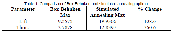
This result suggests that the simulated annealing approach to optimization is far superior to a simple maximum selection from a Box-Behnken design of experiments. The simulated annealing algorithm uses the response surface to more completely explore the available wing paths, and thus settles on a better solution.
The accuracy of the simulated annealing solution, however, is only as accurate as the response surface representation of the actual data. Additionally, the response surface is limited in accuracy due to a Box-Behnken design of experiments (rather than a full factorial exploration). In order to estimate the accuracy of the response surface representation of actual data the difference between the response surface function and the Box-Behnken data collected was calculated. Table 2 shows this calculation.
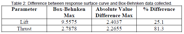
Clearly, the response surface is more accurate in estimating the lift than the thrust. However, this calculation is in no way a full statistical analysis. Further research will be conducted to determine the effectiveness of the current response surface, with improvements as needed.
Conclusion
A mechanism was successfully constructed that allows for the exploration and optimization of flapping with paths. A simulated annealing algorithm was used to achieve an optimal wing path.