Justin Marshall & David Jensen & Fernando Fonseca, Civil and Environmental Engineering
Identification of Problem and Opportunity
When a reinforced concrete beam is loaded it tends to sag or deflect. Because of this deflection, the bottom fibers of the beam are in tension while the top is compressed. Reinforcement (rebar) is placed in beams to resist tensile forces which concrete cannot support. Rebar can have adverse effects under certain conditions. If the concrete cracks, the steel will rust and expand causing increased cracking and strength loss. Other potential problems stem from steel’s density, magnetic properties and conductance. Currently, much research is being done in the area of composite reinforcement to solve these problems. Recent thesis research done at BYU by Rodney Blake has shown that the IsoTruss™-reinforced concrete columns performed exceptionally well in flexure tests. To advance this research, the geometry of the IsoTruss™ will be varied and adapted for inclusion in concrete beams. The replacement of steel with a variation of the basic IsoTruss™ should increase the strength, stiffness and toughness of the beam as well as reducing the beam’s weight.
Technical Approach
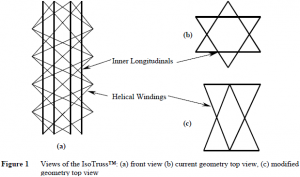
The basic IsoTruss™ is a filament wound 3-D carbon fiber truss. It has 6 equally spaced members that spiral around the central axis clockwise, 6 others that spiral counter-clockwise, and 6 longitudinal members running parallel to the central axis. The combination of these members forms a symmetrical tube with 6 nodes at the top of 6 tetrahedrons lying on the edge of the tube. These nodes form a shape similar to the Star of David. The unique geometry is displayed in Figure 1. The symmetry of the truss renders it both redundant and damage tolerant. The low density of composites and the optimized material placement makes this truss ideal for structural reinforcement. Composites are corrosion resistant, have a low coefficient of thermal expansion, and have an extended life span. The initial findings are that the basic IsoTruss™-reinforced concrete columns sustained greater loads and were stiffer than beams reinforced by an equivalent area of steel.
This variation of the truss will move all 6 nodes to the outer edge of the beam forming more of a rectangle. This will place more material further from the neutral axis of the beam where greater stresses occur. The longitudinal and helical members near the center of the beam will resist shear forces. A diagram of the proposed modification can be seen in Figure 1.
Research Plan
The first phase of this research was the modification of the IsoTruss™ geometry. The modification changed the equilateral triangles in the Star of David to isosceles triangles. The dimensions of the modified truss were 5.2 in by 3 in which is close to the general practice for beam design. Phase 2 was the redesign of the mandrel used to wind the truss. This proved more difficult than was thought and so only one truss was wound and tested on a mandrel manufactured in wood. The third phase of research was the production of trusses and beams. The beam dimensions were 4 in by 6 in by 27 in. One truss was produced and tested using a four point loading system until failure. A 4000psi concrete mix was used for the beam. Throughout the testing, deflections and load was measured so the beam behavior could be accurately modeled. All data will be collected and analyzed for future comparison.
Test Results
The beam held a maximum load of 6550 lb which corresponds to a maximum moment of 26,600 in-lb. The maximum deflection was .34 in at failure with cracking occurring first at a load of 200 lb.
Conclusion
The IsoTrussÔ-reinforced concrete beam was equivalent to a beam with one #3 rebar. This corresponds to a lighter beam with greater corrosion resistance and less labor to insert the reinforcement. The IsoTrussÔ as reinforcement is more beneficial than normal steel reinforcement.

