Jeff Brimhall and Dr. David W. Jensen, Civil And Environmental Engineering
BACKGROUND
The IsoTruss is an innovative structural member made up of a unique geometric configuration and composite material that has tremendous potential for use in civil infrastructure, aerospace and other applications. This unique geometric configuration, which uses minimal material, yet maintains a very high strength. This greatly reduces the weight of the structure and causes the strength-to-weight and stiffness-to-weight ratios to skyrocket.
Another aspect of the IsoTruss that increases the efficiency is the material of which it is made: a carbon fiber and epoxy resin composite. This material has tensile strengths similar to steel at a fraction of the weight. As a result, the IsoTruss offers a solution to various engineering problems. For example, airplane wings, bicycle frames, temporary construction supports, bridges, and satellites all benefit from lightweight and high strength structures.
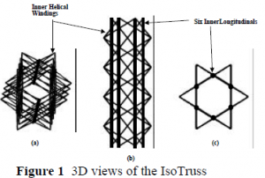
An end view of the IsoTruss reveals two equilateral triangles oriented in opposing directions that are offset a specified distance (see Figure 1). This geometry provides a very rigid and redundant structure. Mere words, however, do not clearly describe the form of the IsoTruss. To fully understand it, one needs to pick up the IsoTruss and twist, pull, and push on it. Since that is not possible in this paper, Figure 1 shows three different views of the IsoTruss, so that the reader may clearly comprehend its geometry.
In order to market the IsoTruss in any of the potential applications, its material properties must be determined. Customers need to know how much load can push on the IsoTruss in compression, pull on it in tension, bend it in flexure and twist it in torsion. This research develops a method for testing the IsoTruss in torsion and determines the maximum torque for different amounts of carbon fiber.
EXPERIMENTAL APPROACH
Due to the unique geometric configuration of the IsoTruss, test fixtures needed to be designed to distribute an applied load into the structure. This included designing endplates for the IsoTruss, a collar for the testing machine and a converter plate between the two. Aluminum end plates shaped identical to the star-like cross-section of the IsoTruss were integrally wound into the composite IsoTruss. With six boltholes, this endplate allows the IsoTruss to be attached to an Instron testing machine, using special collars that were manufactured to achieve the load necessary to fail the IsoTruss.
The test matrix for torsion included seven IsoTruss specimens fabricated using three (3), six (3) and nine (1) wraps of 12K carbon fiber. The number of wraps indicates how many times carbon fiber was wound along each member of the IsoTruss. The purpose of the varied number of wraps was to determine the relation between maximum torque and wraps of carbon fiber. With increased wraps of carbon fiber, the maximum torque was expected to increase.
RESULTS
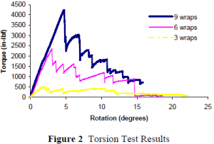
The following figure shows the results of the specimen with maximum values from each of the different wraps in the torsion tests.
CONCLUSIONS
As expected, increasing the amount of carbon fiber wraps increased the maximum torque in a nearly linear fashion. However, the maximum torque was well below the initial predictions. Therefore, either very thick IsoTrusses will have to be used in potential applications to obtain the required strength or the fabrication quality of the IsoTrusses will have to improve.
REFERENCES
- Jensen, David W., Redford, Monica, and Francom, Larry R., “On the Structural Efficiency of Three-Dimensional Isogrid Designs.” Proceedings of the 37th AIAA/ASME/ASCE/AHS/ASC Structures, Structural Dynamics, and Materials Conference, AIAA-96-1508-CP, 1996, pp. 1704-1710.
- Blake, Rodney R., Compression and Flexure of Graphite/Epoxy IsoTruss-Reinforced- Concrete, MS Thesis, Brigham Young University, Provo, Utah, May 1998.
- Weaver, Thomas J, Manufacturing of a Three-Dimensional IsoTruss Structure, BS Honors Thesis, Brigham Young University, Provo, Utah, November 1996.


