C. Porter Bassett and Dr. C. Greg Jensen, Mechanical Engineering
Reverse engineering, or the process of taking an implemented idea and taking it back to the design stage, has many applications in many different types of engineering. One common application of reverse engineering is to take a manufactured part, measure its dimensions and shape, and then make new drawings or Computer-Aided Design (CAD) models of the part. When done manually, this is a very tedious process that includes measuring dimensions and manually inputting them into the CAD program. This also leaves a lot of room for human error either on measuring the part or inputting the dimensions. The reverse engineering of a part can be done automatically though. The Mechanical Engineering department at the University of Victoria has developed a system that measures the shape and size of a part using laser optics and then generates a CAD model of the part.1 This type of automatic reverse engineering is much faster and more accurate than manual reverse engineering.
The Mechanical Engineering Department owns a piece of inspection machinery called the ROI video probe. In essence, the video probe is nothing more than a very good video camera mounted on a measuring table and connected to a computer that drives the camera and analyzes the image. It is designed to visually and automatically inspect many copies of the same part. A program would be written on the computer to inspect the dimensions of certain features of the part. This program can be run again and again on different parts, and the computer can tell whether the part being measured is within dimensional tolerance or not.
Since the video probe can measure features such as points, lines, and arc and save them as a file, I thought that it should be possible to use that data to generate CAD models of the measured parts. This was the goal of this research, to learn how the ROI video probe could be used as a semi-automatic reverse engineering machine. This goal was accomplished.
There are two different ways that I found to export data from the video probe in a format that could be read by a CAD system. One option is to save the part program in Data Exchange Format (DXF), a two-dimensional format that is fairly standard across industry. DXF can be used to save both lines and arcs. Very complicated shapes can be defines using different combinations of lines and arcs. Unfortunately ProEngineer, the CAD system that I used for this research, does not read DXF files very well, so it was necessary to convert the DXF files into IGES, a much more widely accepted file format.
Some shapes are just too complex to accurately define using only lines and arcs. More complex curves are required. The DXF files were not able to export points required to define complex curves. Another method was invented. Using the inspection computer’s ability to formulate an end-of-report data file, I devised a procedure that lets the user export a file that contains horizontal and vertical dimensions for points. A program was written that translates this data file into a format that ProEngineer can read.
Once the outline of a part is in a format that ProEngineer can read, it is merely a matter of building the model around that outline. This is not automatic. It still requires a high level of experience with the CAD system. It is possible, however, to achieve much higher degrees of accuracy using this method that by doing it manually.
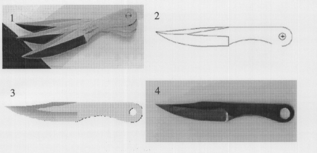
As a research assistant in CB 152, I have already helped other students use this technique. It has been used to reverse engineer a cam for a printer, a mechanical pencil, chess pieces, a knife, and many other items for both class work and personal projects. The ROI video probe is now available as a very accurate reverse engineering tool for all engineering students.
Figure 1: Photograph of knife that was measured on the ROI video probe.
Figure 2: DXF information exported from ROI video probe and imported to ProEngineer Figure 3: Three dimensional ProEngineer model generated using DXF file.
Figure 4: Knife manufactured from ProEngineer model using ProEngineer’s manufacturing module.
Footnotes:
1. Weir, DJ “Reverse Engineering Physical Models Employing Wrap-around B-spline Surfaces and Quadrics” Proceeding of the Institution of Mechanical Engineers Part B: Journal of Engineering Manufacture v2l0 n B2 1996

