
Douglas Bailey and Dr. Stephen Schultz, Electrical and Computer Engineering
Introduction
Shape sensing is useful in a variety of applications including medicine, health monitoring of structures such as offshore oil vessels, windmills, spacecrafts, etc. Knowing an object’s shape allows evaluation of its condition during stress or its position in relation to other objects. One common method of shape sensing involves the use of Fiber Bragg gratings (FBG). FBGs have very high strain sensitivity and thus can be used to measure even the smallest changes in shape.
An FBG is an optical device that acts as a mirror to specific wavelengths of light, while letting other wavelengths pass through. The wavelength that it reflects depends on the strain in the fiber. The shift in wavelength is about 1.2pm/με for most FBGs. By tracking the shifting reflected peak, the strain in the fiber can be measured.
Commonly, FBG peaks in an FBG array are spread out over a wide wavelength range to prevent them from interacting and crossing each other. The more FBG peaks that can be packed into the array, the greater sensitivity it has. As the total number of FBGs and the wavelength range increases, interrogation difficulties emerge such as nonlinearity of broadband sources and filters over a wide wavelength range. In order to avoid these interrogation problems, individual FBG peaks can be packed closer together in wavelength, however at the expense of allowing the overlapping and crossing of two adjacent FBG peaks in certain cases. For example, suppose two adjacent FBG peaks are close in wavelength and large strain is induced in one of them, but not the other. In this case one peak will overlap the other and at one point it will be impossible to detect both peak locations. Both peaks will again be detectable only after the strained FBG peak crosses to the other side of the stationary FBG peak or returns back, but then the two peaks also need to be correctly identified.
Methodology
I proposed and researched different solutions to the problem of detecting and identifying FBG peaks as they cross over each other. For my setup to test my solutions, I spliced two FBGs together. These two FBGs reflected at different central wavelengths. Both were glued to boards so that I could induce strains. I shined a wideband light source through the FBGs, and then used a tunable light filter to interrogate across a wide spectrum of wavelength. I used a photo detector followed by an oscilloscope to retrieve the data. I imported the data into Matlab, where I could analyze it as well as apply my peak estimation algorithms.
My first solution assumed that a peak moves linearly from the moment it becomes obscured by the adjacent peak to the moment when it is detectable again. The algorithm finds the last known location before the crossing and the first known location after the peak has become detectable again and then it linearly interpolates the values between the two points.
The second solution was to measure the width of the FBGs peaks in question. Then, I looked at the profile of when the peaks are crossing each other, and using the known widths of the FBG profiles, I estimated the locations of the peaks.
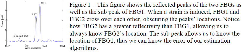
One of the two FBGs that was used in my tests had a very large secondary peak. It was far enough away from the main peaks of the two FBGs that it never crossed. Using this secondary peak as well as the fact that the other FBG had a greater reflectivity, I knew the exact locations of the peaks. In a real world application, many FBGs would be packed close together, and so a secondary peak could not be used to measure the strain in the FBG. However, I could use it with my set up of just two FBGs to find the error of my solutions.
Figure 1 – This figure shows the reflected peaks of the two FBGs as well as the sub peak of FBG1. When a strain is induced, FBG1 and FBG2 cross over each other, obscuring the peaks’ locations. Notice how FBG2 has a greater reflectivity than FBG1, allowing us to always know FBG2’s location. The sub peak allows us to know the location of FBG1, thus we can know the error of our estimation algorithms.
Results
The first solution works best when the peaks cross each other at a constant velocity. In such cases I was able to correctly estimate the locations to within 20 pm of wavelength (17 με). However, when one peak changes direction mid-crossing, I had errors up to 150 pm (125 με).
The second solution, although harder to implement, works about the same as the first solution during constant velocity. However, where the first solution became very inaccurate, the second solution stayed within 30 pm (25 με).
Conclusion
We analyze the possibilities of using multiple FBGs to sense dynamic shape changes by measuring strain induced in FBGs configured in a mesh. Since strain can, in a general case, be different on each FBG, when FBGs are packed tightly in a narrow wavelength range we run into the problem of peaks crossing each other, and it becoming impossible to track their exact location. We propose two solutions. In one solution we present a linear interpolation algorithm to create peak estimates connecting the last point before the crossing to the first point after. The second solution generates peak estimates based off of the width of the peaks. We describe the experimental set up. We show that during a constant velocity crossing of FBG peaks, both solutions work the same. We show that the second solution outperforms the first when there is a change of velocity or direction of either peak during the crossing. The second solution can track the peak with an accuracy of 30 pm (25 με).