Caleb Goates. Dr. Kent Gee and Dr. Tracianne Neilsen, Department of Physics and Astronomy
Introduction
Where is that sound coming from? Acoustic beamforming is a method to determine just that, by recording sound simultaneously with several microphones and finding the delay between the signals. But beamforming can do more than point in the direction sound is coming from: beamforming is often used to discover subtle characteristics of a sound source about which little is known, such as jet aircraft, vibrating car doors, and rockets. In these situations it is helpful to divide the sound into the constituent frequencies and analyze them separately. Beamforming can do so, with one caveat: if you go high enough in frequency that the wavelength of sound is less than two times your microphone separation, there will be false sources in your beamforming results.
This is the problem addressed by my research: How can we use beamforming at frequencies that are higher than that limit? The obvious solution is to simply use more microphones and decrease your microphone spacing, but the ability to go higher than the high-frequency limit, called the spatial Nyquist frequency (𝑓𝑁), opens up a wealth of knowledge available from pre-existing data. This is especially useful when the data is a recording of a one-time event, such as a rocket test. We address this problem by adding in “virtual microphones” that effectively lower the microphone spacing.
Methods and Results
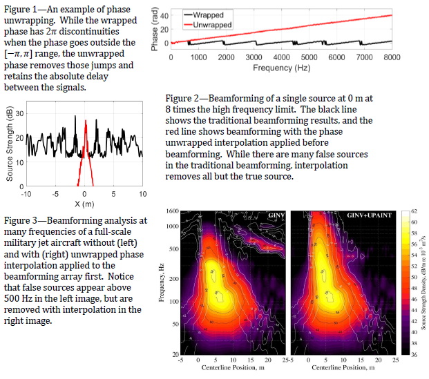
In frequency-domain beamforming, delays between signals are represented as phase differences. The periodic nature of sinusoids cause any calculated phase difference to lie in the [−𝜋,𝜋] range, though the absolute phase delay between to signals could be any number. This absolute phase can be determined from the [−𝜋,𝜋], or wrapped, phase using a process called phase unwrapping. An example is shown in Figure 1. Phase unwrapping is the key to this project. Much research has been done on adding virtual microphones to an array, but never has it been successfully done above 𝑓𝑁. Our method interpolates the magnitude and unwrapped phase of the microphone signals to find the virtual microphone signals. These quantities vary more smoothly than the real and imaginary parts of the signal, which is what is traditionally interpolated.
Once these virtual microphones have been added to the microphone array, beamforming proceeds as if they were all physical microphones. An experiment was designed to test this method, with a single speaker playing noise to be picked up by 22 microphones. We then unwrapped the phase and interpolated both the magnitude and phase to create a total of 216 microphones, real and virtual. The results of this test are shown in Figure 2 at a frequency 8 times the limit caused by the microphone spacing. The places where the source strength is high indicate that a source is present at that location. The actual experiment had a source only at 𝑋=0 m, but the black line indicates that there are many sources. This is what traditional beamforming will tell us at high frequencies. The red line is with interpolation applied first, and it indicates that there is only one source, in the correct location.
The method was also tested on research measurements of a full-scale military jet. In this case the microphone count was increased more than 8 times, to successfully reach 6 times 𝑓𝑁. The results of this beamforming are shown in Figure 3 over several frequencies. The false sources that appear at and above 500 Hz on the left plot are removed in the right plot, which is with interpolation applied.
Conclusions
The unwrapped phase array interpolation (UPAINT) method works well for the cases that were tested in this study. For sources that are broadband and for which the phase can be unwrapped, this method allows for analysis at higher frequencies than are traditionally possible.

