
Paul Bartholomew and Dr. Brian Mazzeo, Department of Electrical and Computer Engineering
On bridge decks, a specified thickness of concrete cover, usually between 2.0 and 3.0 in., is provided over the embedded reinforcing steel as a protective layer. When chloride ions penetrate the concrete cover, corrosion of the reinforcement can occur [1, 2, 3]. Corrosion problems are usually exacerbated in cold regions, where the source of chlorides is usually deicing salts applied to roads during winter conditions to melt ice, and in coastal regions, where exposure to sea water is prevalent. Since corrosion products are generally five to seven times greater in volume than the parent steel, the corrosion process can induce significant tensile stresses inside the concrete. Because concrete is relatively weak in tension, it can then sustain damage in the form of cracking, delamination, and spalling [4, 5, 6, 7]. Because bridge deck failures are commonly linked to elevated chloride concentrations, measuring chloride content is an important goal of many bridge inspection programs.
Concrete resistivity is an important structural health indicator for reinforced concrete structures such as bridge decks. Resistivity testing indirectly measures the ability of concrete to resist chloride ion penetration [8, 9, 10, 11]. It therefore can be used to assess the likelihood of reinforcing steel corrosion to occur [8, 10, 12, 13], where the rate of corrosion is inversely proportional to the electrical resistivity of concrete [8, 10, 12, 13]. Electrical resistivity is the real part of a material’s impedance. This makes the use of impedance spectroscopy an attractive approach because impedance measurements can be performed relatively quickly and easily.
A system as shown in Figure 1 was developed which vertically measures the impedance of the cover concrete on reinforced bridge decks. In the developed system, four points are of particular note. First, the potential ground is the rebar embedded in the bridge deck itself. Because the bridge deck grounding to earth may be highly variable, depending on the continuity of electrical paths from the deck to the bridge foundation, the rebar is always used as a potential reference. Second, a guard ring is necessary to confine the measured currents to the area beneath the probe [14]. For example, when the concrete surface is wet, the guard ring specifically prevents stray currents that may escape from beneath the probe into the surrounding surface water from decreasing the measured impedance of the underlying concrete. Third, through-concrete measurements as obtained with this impedance spectroscopy device are different than traditional two- and four-prong resistivity measurements because the measured current does not travel laterally between the probe tips but vertically through the concrete to the rebar [15]. Fourth, the surface impedance is an important parameter for the measurement [16]. As such a detergent-water solution was used as coupling fluids and an electrode was developed from mechanically roughened aluminum and aluminum screen mesh [17, 18, 19].
During the course of this project, the devolved system was used on small concrete blocks in the lab, on large slabs cut from decommissioned bridge decks, and on bridge decks in the field in both Minnesota and Virginia. In all of these tests, the developed system was able to rank tests and blocks by their chloride concentrations. One comparison which yielded exceptional results will be described.
Three concrete slabs, each measuring 5 ft X 9 ft, were obtained from decommissioned bridge decks on Interstate-15 in Provo, Utah. Two of the slabs were removed from neighboring bridges that were both built in 1964 near 820 North to carry traffic over the Union Pacific Railroad (UPRR) and Utah Transit Authority (UTA) corridors. Both of these decks were constructed using uncoated reinforcing steel and were surfaced with a protective membrane and asphalt overlay several years later in 1972. The third slab was removed from a bridge built in 1985 over Center Street. This deck was constructed with epoxy-coated reinforcing steel and was immediately covered with a membrane and asphalt overlay.
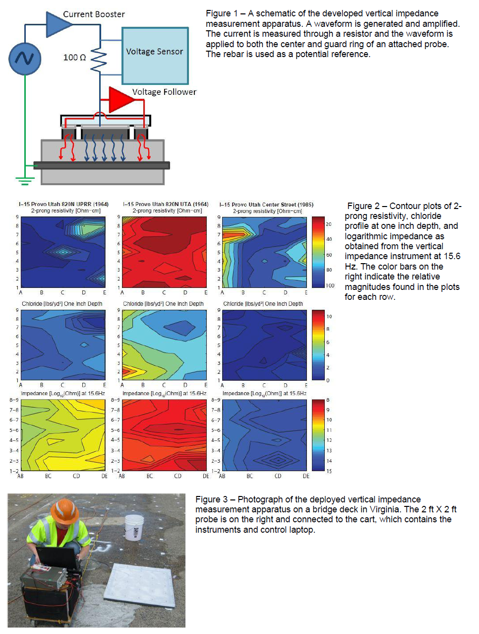
In the laboratory, several tests, which are used to diagnose bridge deck failure in the field, were performed on each of these slabs, including two-prong resistivity testing and chloride concentration testing, which was performed at a depth of 1 in., approximately equal to the midpoint of the cover depths of the slabs. One measurement was obtained from each square foot of each slab, for a total of 45 measurements per test per slab. To determine if the developed impedance testing could be better suited to characterize the slabs, measurements were also taken on each of these slabs. The results will be described and are shown in Figure 2.
Two measurements for 2-prong resistivity are shown in the first row of Figure 2. The UPRR overpass recorded the highest average, while the UTA had the lowest average. The Center Street overpass had an average value which fell between the other two bridges. It is interesting to note that the Center Street Bridge, which has the epoxy coated bar and should provide the most protection to the structure, did not have the highest impedance as measured by the 2-prong resistivity technique, reflecting the horizontal interrogation nature of the 2-prong technique. In fact, these measurements might cause one to be overly concerned about the condition of the deck.
The chloride profile, second row of Figure 2, revealed the amount of chloride ions did indeed diminish as the depth increased. The bridge which had the most chloride ions was the UTA while the Center Street overpass had the least amount and was deemed to be an environment less likely for corrosion.
The vertical impedance meter recorded logarithmic impedance values at 15.6 Hz, shown in the third row of Figure 2, determined that the Center Street overpass to have the highest impedance and the one most likely to be resistant to corrosion. This coincides with the chloride concentration which also had the lowest concentrations for this sample. The UTA bridge had the lowest impedance values and as such should be the most likely environment for corrosion, which also coincide with both the 2-prong resistivity technique which had the lowest impedance values for this sample, and the chloride profile, which had the highest measurements for this sample.
In conclusion of this testing, it was determined that the developed system may be better suited to characterize the deterioration of bridge decks rather than the widely accepted 2-prong resistivity technique. The full progress and findings of this project are being prepared to be submitted as an article to the Review of Scientific Instruments.
References
- X. Shi, L. Fay, Z. Yang and T. Nguyen, “Corrosion of deicers to metals in transportation infrastructure: Introduction and recent developments,” Corrosion Reviews, vol. 27, pp. 23-52, 2009.
- C. Andrade, M. Keddam, X. R. Novoa, M. C. Perez, C. M. Rangel and H. Takenouti, “Electrochemical behaviour of steel rebars in concrete: influence of environmental factors and cement chemistry,” Electrochimica Acta, vol. 46, pp. 3905-3912, 2001.
- G. K. Glass and N. R. Buenfeld, “The Presentation of Chloride Threshold Level for Corrosion of Steel in Concrete,” Corrosion Science, vol. 39, no. 5, p. 1001–1013, 1997.
- S. Mindess, J. F. Young and D. Darwin, Concrete, Second ed., Upper Saddle River, NJ: Prentice Hall, 2003.
- J. H. Bungey and S. G. Millard, Testing of Concrete in Structures, Cambridge: Chapman and Hall, 1996.
- W. S. Guthrie and T. M. Pinkerton, “Sensitivity of Half-Cell Potential Measurements to Properties of concrete Bridge Decks,” Provo, UT, 2008.
- H. Bohni, Corrosion in Reinforced Concrete Structures, Boca Raton, FL: CRC Press, Inc., 2005.
- W. S. Guthrie and R. S. Tuttle, “Condition Analysis of Concrete Bridge Decks in Utah,” Provo, 2006.
- W. S. Guthrie, E. T. Linford and D. Eixenberger, “Development of an Index for Concrete Bridge Deck Management in Utah,” Transportation Research Record: Journal of the Transportation Research Board, vol. 1991, pp. 35-42, 2007.
- J. Hema, W. S. Guthrie and F. Fonseca, “Concrete Bridge Deck Condition Assessment and Improvement Strategies,” Provo, 2005.
- V. M. Malhotra and N. J. Carino, Handbook on Nondestructive Testing of Concrete, Boca Raton, FL: CRC press, Inc., 1991.
- H. W. Song and V. Saraswathy, “Corrosion Monitoring of Reinforced Concrete Structures – A Review,” International Journal of Electrochemical Science, vol. 2, pp. 1-28, 2007.
- D. A. Whiting and M. A. Naji, “Electrical Resistivity of Concrete-A Literature Review,” Skokie, IL, 2003.
- W. C. Heerens, “Application of capacitance techniques in sensor design,” J. Phys. E: Sci. Instrum., vol. 19, pp. 897-906, 1986.
- Smits, “Measurement of Sheet Resistivities with the Four-Point Probe,” Bell System Technical Journal, pp. 711-718, May 1958.
- S. G. Millard, J. A. Harrision and K. R. Gowers, “Practical Measurement of Concrete Resistivity,” British Journal of Non-destructive Testing, vol. 33, p. 59–63, 1991.
- F. Pizzitutti and F. Bruni, “electrode and interfacial polarization in broadband dielectric spectroscopy measurements,” Review of Scientific Instruments, vol. 72, no. 5, pp. 2502-2504, May 2001.
- B. L. Mellor, E. Cruz Cortes, S. Khadka and B. A. Mazzeo, “Increased bandwidth for dielectric spectroscopy of proteins through electrode surface preparations,” Review of Scientific Instruments, 2012.
- P. Mirtaheri, S. Gvimnes and O. Martinsen, “Electrode Polarization Impedance in Weak NaCl Aqueous Solutions,” IEEE Transactions on Biomedical Engineering, vol. 52, no. 12, p. 2093–2099, 2005.